This thread has been locked.

If you have a related question, please click the "Ask a related question" button in the top right corner. The newly created question will be automatically linked to this question.

Optimizing AM335x IO Power in DeepSleep0

Other Parts Discussed in Thread: TPS65910, TPS65217, TPS51200, TLV320AIC26, STRIKE, TPS65910A

When using the spreadsheet from http://processors.wiki.ti.com/index.php/Optimizing_AM335x_IO_Power_in_DeepSleep0

If the pinmux is set to gpio (MUX_MODE7) and it says the DeepPad state is OUTPUT LOW.  Does that mean it will ignore the PIN_INPUT part of the pinmux? 

If Pinmux Change is required how do I determine which mux mode to change it to?  Especially if pinmux is already gpio...

If the pinmux is set to gpio and the spreadsheet claims the DeepPad state is OUTPUT LOW, should I set the sleep pinmux to PIN_OUTPUT?

  • Hi,

    What software are you using?
  • Sorry this was in response to some advice Brad offered about reducing power usage on the 335x when in sleep mode. e2e.ti.com/.../1663292

    I am using the spreadsheet mentioned in the link above to configure pinmuxes in the 3.14 kernel.
  • Jonathan Cormier said:
    If the pinmux is set to gpio (MUX_MODE7) and it says the DeepPad state is OUTPUT LOW.  Does that mean it will ignore the PIN_INPUT part of the pinmux? 

    Correct, the pin will be driving the pin low, regardless of rxactive in the pin mux register.

    Jonathan Cormier said:
    If Pinmux Change is required how do I determine which mux mode to change it to?  Especially if pinmux is already gpio...

    It's probably best if you tell me which pin you're looking at, and how that pin is connected on your board (e.g. if it's an input, is there an external device driving the pin or perhaps an external pullup)?

  • The gpmc_wpn pin has a pull up resistor attached to it. The spreadsheet says the DeepSleep Pad state is output low and requires a pinmux change with no pull.
  • I suggest mux mode 4 (mmc2_sdcd). To be honest I'm not sure of the precise timing of when this gets flipped. For cases like this where you have an input I usually try to pick a different pin function that's also an input to avoid driving something momentarily on the pin. As a general note we don't guarantee "glitchless pin mux transitions" so there could possibly be a glitch as this happens. Since these pins that require a mux change tend to be few and far between it might be a good idea to check it out on a scope.
  • Brad Griffis said:
    I suggest mux mode 4 (mmc2_sdcd). To be honest I'm not sure of the precise timing of when this gets flipped. For cases like this where you have an input I usually try to pick a different pin function that's also an input to avoid driving something momentarily on the pin. As a general note we don't guarantee "glitchless pin mux transitions" so there could possibly be a glitch as this happens. Since these pins that require a mux change tend to be few and far between it might be a good idea to check it out on a scope.


    Brad,

    The majority of the 335x device trees seem to be switching pinmuxes to gpio during sleep. Is this not recommended then?

    Also changing the gpmc_wpn pinmux to mmc2_sdcd didn't seem to have any noticeable affect on power usage.

  • Jonathan Cormier said:
    The majority of the 335x device trees seem to be switching pinmuxes to gpio during sleep. Is this not recommended then?

    That is true.  I asked the software team for details on that decision.  I'm not aware of anything that forces you to change the mux mode, except for circumstances like you mentioned here where certain pins might drive the wrong direction during DS0.  I'll try to get some more info.

  • Jonathan Cormier said:

    The majority of the 335x device trees seem to be switching pinmuxes to gpio during sleep. Is this not recommended then?

    Also changing the gpmc_wpn pinmux to mmc2_sdcd didn't seem to have any noticeable affect on power usage.

    Decided to do a quick test and reset all sleep pinmuxes by copying their default pinmux into the sleep pinmuxes. Effectively disabling all the sleep pinmuxing.  Sleep power usage dropped from 214mW to 209mW. So all the sleep pinmuxing we copied from the evm's dts were causing more harm than good even after spending a day making sure the DeepSleep Pad states and Pull Settings where conflicting with hardware.  So that seems pretty conclusive, changing your pinmuxing to gpio during sleep is not a good idea.

    From this newer low power usage, I rewalked through the spreadsheet and changed the sleep pinmuxes to fix conflicts with the DeepSleep Pad State and DeepSleep Pull Settings.  Sleep power usage is now down to 207mW, the only change that seemed to have an effect was fixing the gpmc_wpn sleep pinmux.

    My original sleep power usage was 229mW which got reduced to 215mW by changing the xdma_event_intr0 default pinmux to gpio instead of its default.


    207mW is still ~60mW higher than our DDR2 rev1.0 module.  Though we still have to try to do the DDR_VTT disabled mod and look at those eratas.

  • What voltage do you measure on vdd_mpu and vdd_core? Is the main clock (e.g. 24 MHz crystal) disabled once you achieve DS0?
  • In mem sleep:
    VCORE_1P1: 1.140V
    VMPU_1P1: 0.957V

    We are using a 24Mhz silicon clock oscillator input into XTALIN powered from VDIG2_1P8. It is not being powered off or put into standby when going into sleep mode.

    Looking at our DDR2 modules, they still use the crystal oscillator so probably don't stay active.
  • I was able to manually put the oscillator into standby mode (grounded the standby pin) while in sleep mode. Power usage dropped from 206mW to 187mW (19mW). After bringing the oscillator out of standby the power went back up and I was able to successfully resume the device.
  • What kind of power savings can I expect if I fix the CM3 code to reduce the VDD_CORE voltage like it does on the EVM?

    Also is there an internal pullup for XTALIN when in deepsleep? I.E. Is it enough to remove power from the oscillator or do I need to keep it powered and put it into standby to ensure it isn't back powered.
  • Jonathan Cormier said:
    What kind of power savings can I expect if I fix the CM3 code to reduce the VDD_CORE voltage like it does on the EVM?

    Since the bulk of the power is already physically cut when PD_PER is powered down, there's not a whole lot of power to save by reducing that voltage.  I would estimate you're looking at <1mW.

    Jonathan Cormier said:
    Also is there an internal pullup for XTALIN when in deepsleep? I.E. Is it enough to remove power from the oscillator or do I need to keep it powered and put it into standby to ensure it isn't back powered.

    The data sheet states, "An internal 15 kohm pull down is turned on when the oscillator is disabled."  How are you planning to remove power, i.e. what in your system will remove power during the shutdown sequence, and what will reapply power when you need to power back up?

  • Currently the oscillator is powered via VDIG2. Turning this off will also power off VDDS_OSC, VDDS_PLL_CORE_LCD, VDDS_PLL_DDR, VDDS_PLL_MPU, VDDS_SRAM_CORE_BG, and VDDS_SRAM_MPU_BB. Which I'm assuming is a no go. So alternatively we can use VDIG1 (after hardware spin) to either power the oscillator or to control its standby pin. Then I'd have to fix the CM3 code so it turns off VDIG1 and turns it back on. Similar to how the VDD_Core voltage is changed.
  • Jonathan Cormier said:
    Then I'd have to fix the CM3 code so it turns off VDIG1 and turns it back on. Similar to how the VDD_Core voltage is changed.

    I don't think that's feasible, as the M3 needs that clock to be alive in order to run any code!  When using a crystal, the start/stop happens in hardware.

  • Hmm that is a problem.  Is there some other way to disable/enable this oscillator then?

  • This only works when you're using a crystal.  In the AM437x we added a clkreq pin to address this scenario.  I don't know of a way to do it on AM335x.

  • We modded our board to disable DDR_VTT when CKE is low.  Power usage during sleep is now 194mW, a roughly 12mW savings.

    I then manually put the oscillator into standby mode and power usage dropped to 175mW.  This is still 30mW higher than the power usage we were seeing with the DDR2 3359 GX module.  We are a lot closer though so atleast there is that.

  • Have you checked the state of DDR_PHY_CTRL_1[20] reg_phy_enable_dynamic_pwrdn? It should be set to 1 (always). If it's not, you'll see a decent chunk of power consumption (~10mW?).

    Are you able to figure out the distribution of current breakdown? If for example there is a specific rail known to be consuming a lot of power then we could look at some things more carefully. For example, if a specific VDDSHVx rail is consuming a lot of power we could more carefully look at each and every pin associated with that rail.
  • Brad Griffis said:
    Have you checked the state of DDR_PHY_CTRL_1[20] reg_phy_enable_dynamic_pwrdn? It should be set to 1 (always). If it's not, you'll see a decent chunk of power consumption (~10mW?).

    Good catch.  Found the following commit that does what you mention. 

    http://lists.denx.de/pipermail/u-boot/2013-March/149219.html

    Enabling this on our module gave me a power savings of ~40mW during system idle.  In mem sleep I see a power reduction of ~6mW. Down to 188mW.

    Brad Griffis said:

    Are you able to figure out the distribution of current breakdown? If for example there is a specific rail known to be consuming a lot of power then we could look at some things more carefully. For example, if a specific VDDSHVx rail is consuming a lot of power we could more carefully look at each and every pin associated with that rail.

    We have a plan to replace some ferrite beads on each power rail with appropriate resistors so we can measure individual currents.  Will look into this.

  • I was using "devmem2 0x4c0000e4 w 0x100007" to enable the dynamic powerdown bit. And noticed that if I slept twice in a row the second sleep was much lower (145mW). Updated u-boot and had it set the bit and sleep goes to 145mW on first sleep.

    Also noticed that after resuming from sleep idle power usage is ~72mW lower.  I suspect something must be getting disabled and then not re-enabled but so far haven't found anything not working...  This has been happening for quite a while so not related to the powerdown bit change.

  • I redid my testing and found out that standby now isn't working. The DDR reset line is now going low when entering standby but not when entering mem. I switched to a module that didn't have the VTT disable rework and standby works on that module. Not sure if disabling VTT could affect the reset line and why it only is affected in standby and not mem.
  • Please re-check your last few changes to identify precisely where this was introduced.
  • Brad Griffis said:
    Please re-check your last few changes to identify precisely where this was introduced.

    I went back to an old kernel and u-boot and the problem persisted.  Then switched back to the latest software.  Had the VTT mod changed so the enable was connected to 1.5V instead of CKE. After which standby mode started working again.

    Planning on putting the DDR reset pullup back on and seeing if that makes a difference, since the EVM does have the pullup so perhaps it was there for a reason.

  • Jonathan Cormier said:
    I went back to an old kernel and u-boot and the problem persisted.  Then switched back to the latest software.  Had the VTT mod changed so the enable was connected to 1.5V instead of CKE. After which standby mode started working again.

    Wow, you got a lot done in record time!  That's interesting and a bit surprising that the DDR_RESET pullup seems to make a difference.  Can you capture it on a scope (perhaps relative to CKE) for standby and mem?  I'm trying to understand if it drives low, slowly discharges low, sits at an intermediate voltage, etc.

  • Brad Griffis said:

    Wow, you got a lot done in record time!  That's interesting and a bit surprising that the DDR_RESET pullup seems to make a difference.  Can you capture it on a scope (perhaps relative to CKE) for standby and mem?  I'm trying to understand if it drives low, slowly discharges low, sits at an intermediate voltage, etc.

    I just had the DDR_RESET 10k pullup put on and reactivated the mod. Now during standby I don't see the RESET go low but its still unable to resume from standby. The power usage drops when entering standby but doesn't go all the way back up when it tries to resume. Very similar to when we were corrupting the DDR contents before.  mem sleep still works as expected.


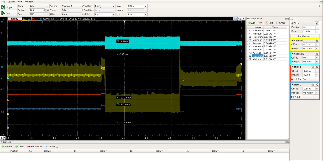
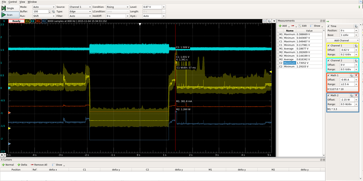
    C1/M1/M2 are module power usage

    C2 is the DDR_RESET signal. Put it into Min/Max mode to catch any dips.

    This is what the same thing for mem sleep looked like

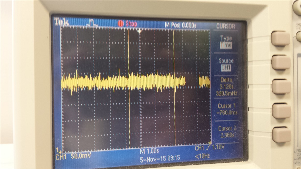
  • Switched to using a real oscilloscope instead of a usb oscilloscope.  The noise seen above doesn't change between sleep and running.  On the scope, RESET is bouncing between 1.48V and 1.56V. There was no noticeable difference between standby and mem sleep.  Also after removing the RESET pullup, I am unable to reproduce the RESET going low.  Its possible that I slid off the pad when I tried to activate standby mode before.


    Shows DDR RESET.  Sleep mode was active in-between cursors.

  • Alright got some strange new information. I decided to use the JTAG interface to dump the memory to verify if DDR was being reset like before. But low and behold I found that if I dumped the memory before going to sleep. When I resumed it worked correctly. Tested this a couple times and it doesn't work 100% but was reproduceable.

    Was able to dump memory before standby and after a failed resume. The first 10K of memory that was dumped matches, so It doesn't look like memory contents are getting corrupted.
  • The screenshot from your scope looks like it's just "scope noise". That's usually related to the grounding of the scope probe. Do you see similar noise on other DDR signals (e.g. CKE, etc.)?

    So it sounds like the issue where DS0 worked but standby failed may have been related to a bad probe connection. That said, I'm unclear as to what issue you're currently having.
  • Brad Griffis said:
    The screenshot from your scope looks like it's just "scope noise". That's usually related to the grounding of the scope probe. Do you see similar noise on other DDR signals (e.g. CKE, etc.)?

    So it sounds like the issue where DS0 worked but standby failed may have been related to a bad probe connection. That said, I'm unclear as to what issue you're currently having.

    Agreed about the noise.  Not sure why it becomes so much more pronounced on the usb scope but its likely to be more susceptible from noise would be my guess.

    Alright lets recap. 

    We are currently able to go into "mem" sleep and resume without issue.  But when resuming from "standby" the processor doesn't recover.

    * If I keep VTT from being disabled then standby works.

    * Also if I use JTAG to dump the memory before standby and then during standby, it will resume successfully most of the time.

    * When standby doesn't resume, I am able to verify using JTAG that at least the first 10K of memory is still intact.

  • Can you please report the value of these registers for your two scenarios (i.e. during standby in one case and from the M3 just before DS0 in the other):

    * ddr_cmd0_ioctrl 0x44E11404
    * ddr_cmd1_ioctrl 0x44E11408
    * ddr_cmd2_ioctrl 0x44E1140C
    * ddr_data0_ioctrl 0x44E11440
    * ddr_data1_ioctrl 0x44E11444
  • These were all grabbed from the CTT JTAG script. For the DS0 case, you want me to debug the M3 and stop it right before the DS0 handler?

    Before Standby:
    0x44e00404 0x00000002
    0x44e00408 0x00030000
    0x44e0040c 0x00000002
    0x44e00440 0x00019017
    0x44e00444 0x00000000

    During Standby:
    0x44e00404 0x00000002
    0x44e00408 0x00030000
    0x44e0040c 0x00000002
    0x44e00440 0x00019017
    0x44e00444 0x00000000

    Broken Resume:
    0x44e00404 0x00000002
    0x44e00408 0x00030000
    0x44e0040c 0x00000002
    0x44e00440 0x00019017
    0x44e00444 0x00000000
  • Woops off by 0x11000

  • So for the standby case, were you able to read the registers *during* standby (e.g. through the DAP)? For DS0 it would be good to capture the data somewhere in the M3 handler because as I recall the A8 adjusts those values late in the suspend sequence (or at least it used to).

    By the way, which kernel are you using right now? Is this behavior observed even on the latest 4.1 kernel?
  • PS. My "DDR script" should pull these values (not the CTT script). Check out the dss file referenced here:

    processors.wiki.ti.com/.../AM335x_Clock_Tree_Tool
  • Brad Griffis said:
    So for the standby case, were you able to read the registers *during* standby (e.g. through the DAP)? For DS0 it would be good to capture the data somewhere in the M3 handler because as I recall the A8 adjusts those values late in the suspend sequence (or at least it used to).

    By the way, which kernel are you using right now? Is this behavior observed even on the latest 4.1 kernel?

    I have been testing with the 3.14 kernel.  Tried booting the 4.1 kernel last week but got no output after u-boot printed "Starting kernel..." so I shelved it for later.  Any ideas about this?

    Just tested the 3.2 kernel and it resumes from standby without trouble.

  • 3.14 kernel

    Before Standby:
    0x44e11404 0x0000018b
    0x44e11408 0x0000018b
    0x44e1140c 0x0000018b
    0x44e11440 0x0000018b
    0x44e11444 0x0000018b

    During Standby:
    0x44e11404 0x0000018b
    0x44e11408 0x08000000
    0x44e1140c 0xf7ffffff
    0x44e11440 0x3ff00003
    0x44e11444 0x3ff00003

    After Successful Resume (Because of JTAG activity?):
    0x44e11404 0x0000018b
    0x44e11408 0x00000000
    0x44e1140c 0x00000000
    0x44e11440 0x00000084
    0x44e11444 0x00000084

    During 2nd Standby:
    0x44e11404 0x0000018b
    0x44e11408 0x08000000
    0x44e1140c 0xf7ffffff
    0x44e11440 0x3ff00003
    0x44e11444 0x3ff00003

    Broken Resume:
    0x44e11404 0x0000018b
    0x44e11408 0x00000000
    0x44e1140c 0x00000000
    0x44e11440 0x00000084
    0x44e11444 0x00000084
  • 3.2 kernel has the following for before, during, and after sleep.
    0x44e11404 0x0000018b
    0x44e11408 0x0000018b
    0x44e1140c 0x0000018b
    0x44e11440 0x0000018b
    0x44e11444 0x0000018b
  • At what point during the resume were you checking the registers? For the resume I would expect that once the A8 is operational that all the registers would revert back to 0x18B. Is that not happening? For example, when you get to the next suspend/resume sequence are they starting out with the other values? I need to look into the specific values to see how all the various signals are being terminated during resume.
  • Brad Griffis said:
    At what point during the resume were you checking the registers? For the resume I would expect that once the A8 is operational that all the registers would revert back to 0x18B. Is that not happening? For example, when you get to the next suspend/resume sequence are they starting out with the other values? I need to look into the specific values to see how all the various signals are being terminated during resume.

    I just used the JTAG scripts and have not modified the M3 code. So the numbers are at whatever they settled at.  I.E. The After number was  when the terminal reappears and the broken numbers was after it failed to come back.  So yes it doesn't look like some of the registers are getting set back.  Though even with that it did come back out of standby once...

    PS: I posted the 3.2 values but they got sent for moderation. Apparently you can't post twice without triggering moderation.  Anyways the values stayed at 0x18B during all stages.

  • FYI, I just made an edit to a post in our other thread:

    e2e.ti.com/.../1660440

    Sorry to change course on you, but after extensive discussion with the factory team we do not think that controlling VTT with the CKE pin is a robust solution. I'd like to advise you to use a GPIO for this purpose. Sorry to change this on you. Hopefully I have alerted you before you have submitted files for your next board spin.
  • Brad Griffis said:
    FYI, I just made an edit to a post in our other thread:

    Sorry to change course on you, but after extensive discussion with the factory team we do not think that controlling VTT with the CKE pin is a robust solution. I'd like to advise you to use a GPIO for this purpose. Sorry to change this on you. Hopefully I have alerted you before you have submitted files for your next board spin.

    We were waiting for testing to finish before working on the board spin so thats fine.

    Note that the StarterKit which has this configuration also has the DDR_RESET pullup.  Going to assume for now that its not required.

    If I remember correctly the gpio is controlled from the Sleep33xx.S code.  Is this gpio configurable? I'm assuming the gpio has to be on the gpio0 bank?

    We currently have the VTT_EN tied to VDIG1 on the PMIC. Would it be enough to instruct the PMIC to turn off VDIG1?  I'm thinking about configuring the PMIC to disable VDIG1 when its SLEEP pin is activated, then we would just need to pull the SLEEP pin low. Should this work?

  • Jonathan Cormier said:
    Note that the StarterKit which has this configuration also has the DDR_RESET pullup.  Going to assume for now that its not required.

    As a safety, you may want to have a "DNP" pull-up on the PCB.  It shouldn't be needed though.

    Jonathan Cormier said:
    If I remember correctly the gpio is controlled from the Sleep33xx.S code.  Is this gpio configurable? I'm assuming the gpio has to be on the gpio0 bank?

    For Processor SDK 1.00 (3.14 kernel) and Processor SDK 2.00 (4.1 kernel) the VTT pin is selected inside the dts file:

            ddr3_vtt_toggle: ddr3_vtt_toggle {
                    pinctrl-single,pins = <
                            0x164 0x7       /* ecap0_in_pwm0_out.gpio0_7, OUTPUT | MODE7 */
                    >;
            };

            pinctrl-0 = <&gpio_keys_s0 &clkout2_pin &ddr3_vtt_toggle>;

    &wkup_m3 {
            ti,needs-vtt-toggle;
            ti,vtt-gpio-pin = <7>;
            ti,scale-data-fw = "am335x-evm-scale-data.bin";
    };

            vtt_fixed: fixedregulator@3 {
                    compatible = "regulator-fixed";
                    regulator-name = "vtt";
                    regulator-min-microvolt = <1500000>;
                    regulator-max-microvolt = <1500000>;
                    gpio = <&gpio0 7 GPIO_ACTIVE_HIGH>;
                    regulator-always-on;
                    regulator-boot-on;
                    enable-active-high;
            };

    Yes, that needs to be from GPIO 0.

    Jonathan Cormier said:
    We currently have the VTT_EN tied to VDIG1 on the PMIC. Would it be enough to instruct the PMIC to turn off VDIG1?  I'm thinking about configuring the PMIC to disable VDIG1 when its SLEEP pin is activated, then we would just need to pull the SLEEP pin low. Should this work?

    This sounds like a very difficult way to do it.  I would go with the GPIO...

  • The benefit of using the PMIC would be its already hooked up. GPIOs are already all assigned to the edge connector so we would likely be breaking backwards compatibility.
  • Brad Griffis said:
    Jonathan Cormier
    Note that the StarterKit which has this configuration also has the DDR_RESET pullup.  Going to assume for now that its not required.

    As a safety, you may want to have a "DNP" pull-up on the PCB.  It shouldn't be needed though.

    Jonathan Cormier
    If I remember correctly the gpio is controlled from the Sleep33xx.S code.  Is this gpio configurable? I'm assuming the gpio has to be on the gpio0 bank?

    For Processor SDK 1.00 (3.14 kernel) and Processor SDK 2.00 (4.1 kernel) the VTT pin is selected inside the dts file:

    [...]

    Yes, that needs to be from GPIO 0.

    Jonathan Cormier
    We currently have the VTT_EN tied to VDIG1 on the PMIC. Would it be enough to instruct the PMIC to turn off VDIG1?  I'm thinking about configuring the PMIC to disable VDIG1 when its SLEEP pin is activated, then we would just need to pull the SLEEP pin low. Should this work?

    This sounds like a very difficult way to do it.  I would go with the GPIO...

    Attached script which configures the PMIC:

    pmic_sleep.sh.txt
    #!/bin/sh
    
    set -x
    
    i2cget -f -y 2 0x2d 0x3f
    i2cget -f -y 2 0x2d 0x40
    i2cget -f -y 2 0x2d 0x42
    i2cget -f -y 2 0x2d 0x43
    i2cget -f -y 2 0x2d 0x50
    i2cget -f -y 2 0x2d 0x52
    
    
    # Keep RTC CLKOUT32K alive during sleep
    i2cset -f -y 2 0x2d 0x42 0x40
    # Disable VDIG1 when in SLEEP
    i2cset -f -y 2 0x2d 0x43 0x02
    # Clear pending interrupts
    i2cset -f -y 2 0x2d 0x50 0xff
    i2cset -f -y 2 0x2d 0x52 0xff
    # Enable SLEEP pin
    i2cset -f -y 2 0x2d 0x3f 0x72
    
    i2cget -f -y 2 0x2d 0x3f
    i2cget -f -y 2 0x2d 0x40
    i2cget -f -y 2 0x2d 0x42
    i2cget -f -y 2 0x2d 0x43
    i2cget -f -y 2 0x2d 0x50
    i2cget -f -y 2 0x2d 0x52


    I am using the above mentioned changes to control gpio 19 which i've connected to the PMIC SLEEP pin.


    I am seeing power usage of about 112mW in mem and 136mW in standby.  Standby resume has worked so far using this method.

    Note: About 40mW of the savings is from putting the PMIC into SLEEP mode.

    I haven't completely removed the VTT/CKE mod yet and it looks like even though its disabled its not completely letting the VTT float so some additional power savings may be seen when its removed.

    At 112mW we are still about 90mW higher than the reported DS0 numbers here: processors.wiki.ti.com/index.php/AM335x_Power_Consumption_Summary#DS0

    20mW is due to the 24Mhz clock being on though so only about 70mW difference.

    Next step is to add current sense resistors and measure the power rails.

  • Alright removed the VTT/CKE mod. Now standby isn't working again. Since removing the mod, VTT is able to drop to 0V when it is disabled via PMIC. I suspect this has something to do with suspend failing to resume. When VTT is completely disabled then suspend acts up.

    [EDIT]

    Hardware team confirmed that when VTT/CKE mod was installed VDIG1 wasn't controlling anything. So it was working because I wasn't actually disabling the VTT pullups.  mem power usage matches this assumption.  Power usage when VTT disabled is ~104mW and with VTT enabled is ~110mW.

    So the issue is that standby won't resume when VTT pullups are disabled.

  • Jonathan,

    FYI, I have been working on creating a wiki page to help with debugging suspend/resume issues such as yours:

    processors.wiki.ti.com/.../Debugging_AM335x_Suspend-Resume_Issues

    As part of that effort I have updated some of my scripts for interrogating the DDR pin configuration. I have reproduced your issue that you reported with the ioctrl registers reporting completely different values before/after suspend. I suspect that might be related to the issues you're currently experiencing. I'm working with TI's Linux team to get that issue corrected. My hope is to have a patch that I can post on the wiki page for Processor SDK 2.00 (which likely will be similar for Processor SDK 1.00). I'll send an update once I have a little more info.
  • PS. I would appreciate any feedback you have with respect to the wiki page. I made some fairly substantial updates to all the scripts so you may want to try it out to get a little more insight into the current configuration.
  • Brad Griffis said:
    Jonathan,

    FYI, I have been working on creating a wiki page to help with debugging suspend/resume issues such as yours:

    processors.wiki.ti.com/.../Debugging_AM335x_Suspend-Resume_Issues

    Brad, The wiki page is very nicely layed out and easy to read. 

    • It was my understanding that the CKE pulldown was required and not simply recommended? It should probably be explicitly mentioned that the data manual shows the CKE with pullup which is not good.
    • Could use a short section mentioning the built in VTT-toggle support in SDK 1 and 2, (using the evm-sk.dts as reference?). And in PSP11 3.2 kernel the VTT_toggle gpio is hardcoded to GPIO0_7 in sleep33xx.S line: 262. Though it uses the evm_id to enable this feature.
    • Since most 335x designs probably make use of the TPS65910 or TPS65217.  It may be worth discussing putting them into SLEEP mode.  I'm assuming the TPS65217 has a similar SLEEP mode to the TPS65910.
    • Also some mention of the 24Mhz crystal and how there is no way to disable a chip oscillator. Increases power usage by ~20mW on our board.
    • Also a mention of the DDR_PHY_CTRL_1[20] reg_phy_enable_dynamic_pwrdn
    • A mention of the JTAG being disabled in the 3.14 kernel. Mentioned at bottom of this page. processors.wiki.ti.com/.../AM335x_Clock_Tree_Tool
    • Add link to old power usage PDF? e2e.ti.com/.../3554.sitara_5F00_boot_5F00_camp_5F00_am335x_5F00_pm_5F00_sw_5F00_training.pdf