- Ask a related questionWhat is a related question?A related question is a question created from another question. When the related question is created, it will be automatically linked to the original question.
This thread has been locked.
If you have a related question, please click the "Ask a related question" button in the top right corner. The newly created question will be automatically linked to this question.
Hello,
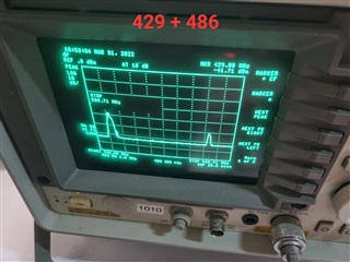
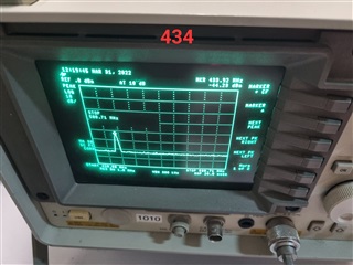
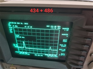
During the last production we had a transmit problem with CC430. We configured our product to use 433MHz band and channel=5, that means Tx frequency should be 434MHz. But around of 10% of produced units, transmit the signal in different frequency:
1) Some units transmit sometimes in frequency around 486MHz and sometimes around 431MHz
2) Some units transmit sometimes in frequency around 486MHz and sometimes correct signal 434MHz
Please note:
1) Attached a screenshot photos from spectrum analyzer of "good" unit, "bad" unit and "semi-bad" unit (unit that sometimes transmit in correct frequency)
2) This product produced around of 8 years, I mean that is not a new design.
3) This issue very similar to the problem that we had about 1.5 years ago with units in 915MHz band. Please see the link below from TI discussion forum:
Thank you,
Alex Katsovich
ATE Engineer, Tel Aviv R&D Site
Centrica Business Solutions
M +972-52-8554528
W centricabusinesssolutions.com
Centrica | 15 Atir Yeda St. | Kfar Saba | 4464312 | Israel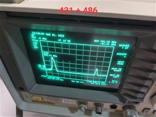
Hello,
Additional test was done to transmit in the 915MHz band and the outcome was around 886MHZ + around 911MHz transmission (transmission was not narrow as expected . As I see it in this case the delta is 26MHz and in the EU band is 2x26MHz. please, advise if this kind of behavior was observed in the past or during development.
BR,
Alfred.
Did you manage to find out the root cause for the problem you saw on 868 MHz for 1.5 years ago?
I don't see any reason why the CC430 should start sending on the wrong frequency for a product that has been is stable production. On the old thread I asked you if "Are you able to test the failing boards with SmartRF Studio? " but didn't get any reply on this. Are you able to do this?
Hello,
Thanks for your prompt feedback.
Can you please, elaborate about SmartRF Studio tool? I assume it is SW that we need to install. Can it work on our product? which connection we need for it?
BR,
Alfred.
Studio:
https://www.ti.com/tool/SMARTRFTM-STUDIO
You would also need a MSP-FET debugger, see https://e2e.ti.com/support/wireless-connectivity/other-wireless-group/other-wireless/f/other-wireless-technologies-forum/153992/msp430-jtag-tiny-and-smartrf-studio as one thread that covers this.
Hello,
I am working to get the debugger and have the SmartRF Studio you mentioned. In parallel, I discussed internally with our FW engineer about the RF settings and was told that they were selected using SmartRF Studio. Please, see below 433MHZ & 915MHZ settings:
//////////////////////////
// 915 Mhz //
//////////////////////////
#ifdef MOD_2GFSK_38_4KBPS
// Chipcon
// Product = CC430Fx13x
// Chip version = C (PG 0.7)
// Crystal accuracy = 10 ppm
// X-tal frequency = 26 MHz
// RF output power = 0 dBm
// RX filterbandwidth = 101.562500 kHz
// Deviation = 19 kHz
// Datarate = 38.383484 kBaud
// Modulation = (1) GFSK
// Manchester enable = (0) Manchester disabled
// RF Frequency = 914.999969 MHz
// Channel spacing = 199.951172 kHz
// Channel number = 0
// Optimization = -
// Sync mode = (3) 30/32 sync word bits detected
// Format of RX/TX data = (0) Normal mode, use FIFOs for RX and TX
// CRC operation = (1) CRC calculation in TX and CRC check in RX enabled
// Forward Error Correction =
// Length configuration = (1) Variable length packets, packet length configured by the first received byte after sync word.
// Packetlength = 61
// Preamble count = (2) 4 bytes
// Append status = 1
// Address check = (0) No address check
// FIFO autoflush = 0
// Device address = 0
// GDO0 signal selection = ( 6) Asserts when sync word has been sent / received, and de-asserts at the end of the packet
// GDO2 signal selection = (41) RF_RDY
static const RF_SETTINGS s_rfSettings_915 = {
0x08, // FSCTRL1 Frequency synthesizer control. FREQ_IF=8
0x00, // FSCTRL0 Frequency synthesizer control.
0x23, // FREQ2 Frequency control word, high byte.--+
0x31, // FREQ1 Frequency control word, middle byte. +- Carrier=914.999969 Mhz
0x3B, // FREQ0 Frequency control word, low byte.---+
0xCA, // MDMCFG4 Modem configuration.
0x83, // MDMCFG3 Modem configuration.
0x93, // MDMCFG2 Modem configuration. 2-GFSK + 4 bytes Sync
0x22, // MDMCFG1 Modem configuration. 4 bytes Preambale Channel spacing 199.951 Khz
0xF8, // MDMCFG0 Modem configuration. //10
0x00, // CHANNR Channel number.
0x34, // DEVIATN Modem deviation setting (when FSK modulation is enabled).
0x56, // FREND1 Front end RX configuration.
0x10, // FREND0 Front end TX configuration.
0x18, // MCSM0 Main Radio Control State Machine configuration.
0x16, // FOCCFG Frequency Offset Compensation Configuration.
0x6C, // BSCFG Bit synchronization Configuration.
0x43, // AGCCTRL2 AGC control.
0x40, // AGCCTRL1 AGC control.
0x91, // AGCCTRL0 AGC control. //20
0xE9, // FSCAL3 Frequency synthesizer calibration.
0x2A, // FSCAL2 Frequency synthesizer calibration.
0x00, // FSCAL1 Frequency synthesizer calibration.
0x1F, // FSCAL0 Frequency synthesizer calibration.
0x59, // FSTEST Frequency synthesizer calibration.
0x81, // TEST2 Various test settings.
0x35, // TEST1 Various test settings.
0x09, // TEST0 Various test settings.
0x47, // FIFOTHR RXFIFO and TXFIFO thresholds.
0x29, // IOCFG2 GDO2 output pin configuration. //30
0x06, // IOCFG0 GDO0 output pin configuration. Refer to SmartRF® Studio User Manual for detailed pseudo register explanation.
0x04, // PKTCTRL1 Packet automation control.
0x05, // PKTCTRL0 Packet automation control.
0x00, // ADDR Device address.
0x78 // PKTLEN Packet length. //35
};
#elif defined(MOD_2GFSK_250KBPS) //250K 2GFSK 915Mhz highest sensitivity
static const RF_SETTINGS s_rfSettings_915 = {
0x0C, // FSCTRL1 Frequency Synthesizer Control
0x06, //0x2D, // IOCFG0 GDO0 Output Configuration
0x00, // FSCTRL0 Frequency Synthesizer Control
0x23, // FREQ2 Frequency Control Word, High Byte
0x31, // FREQ1 Frequency Control Word, Middle Byte
0x3B, // FREQ0 Frequency Control Word, Low Byte
0x2D, // MDMCFG4 Modem Configuration
0x3B, // MDMCFG3 Modem Configuration
0x13, //0x93, //0x13, //0x10, // MDMCFG2 Modem Configuration
0x22, // MDMCFG1 Modem Configuration
0xF8, // MDMCFG0 Modem Configuration
0x00, // CHANNR Channel Number
0x62, // DEVIATN Modem Deviation Setting
0xB6, // FREND1 Front End RX Configuration
0x10, // FREND0 Front End TX Configuration
0x10, // MCSM0 Main Radio Control State Machine Configuration
0x1D, // FOCCFG Frequency Offset Compensation Configuration
0x1C, // BSCFG Bit Synchronization Configuration
0xC7, // AGCCTRL2 AGC Control
0x00, // AGCCTRL1 AGC Control
0xB0, // AGCCTRL0 AGC Control
0xEA, // FSCAL3 Frequency Synthesizer Calibration
0x2A, // FSCAL2 Frequency Synthesizer Calibration
0x00, // FSCAL1 Frequency Synthesizer Calibration
0x1F, // FSCAL0 Frequency Synthesizer Calibration
0x59, // FSTEST Frequency Synthesizer Calibration Control
0x88, // TEST2 Various Test Settings
0x31, // TEST1 Various Test Settings
0x09, // TEST0 Various Test Settings
0x07, // FIFOTHR RX FIFO and TX FIFO Thresholds
0x29, //0x0D, //0x0B, // IOCFG2 GDO2 Output Configuration Asynchronous data mode
0x04, // PKTCTRL1 Packet Automation Control
0x05, //0x45, //0x35, //0x05, //0x35, //0x15, //0x12, // PKTCTRL0 Packet Automation Control
0x00, // ADDR Device Address
0x3F //0x78 //0xFF, // PKTLEN Packet Length
};
#endif
//////////////////////////
// 433 Mhz //
//////////////////////////
#ifdef MOD_2GFSK_38_4KBPS
#error "For 433Mhz band ,2GFSK @ 38.4KBPS is not yet implemented !!!"
#elif defined(MOD_2GFSK_250KBPS) //250K 2GFSK 433Mhz highest sensitivity
static const RF_SETTINGS s_rfSettings_433 = {
//0x08, // 0x0C, // FSCTRL1 Frequency Synthesizer Control
0x0C,//
//0x00,//0x2D, // IOCFG0 GDO0 Output Configuration
0x06,
0x00, // FSCTRL0 Frequency Synthesizer Control
0x10, // FREQ2 Frequency Control Word, High Byte
0xA7, // FREQ1 Frequency Control Word, Middle Byte
0x62, // FREQ0 Frequency Control Word, Low Byte
0x2D, // MDMCFG4 Modem Configuration
0x3B, // MDMCFG3 Modem Configuration
0x13, //0x10, // MDMCFG2 Modem Configuration
0x22, // MDMCFG1 Modem Configuration
0xF8, // MDMCFG0 Modem Configuration
0x00, // CHANNR Channel Number
0x62, // DEVIATN Modem Deviation Setting
0xB6, // FREND1 Front End RX Configuration
0x10, // FREND0 Front End TX Configuration
0x10, // MCSM0 Main Radio Control State Machine Configuration
0x1D, // FOCCFG Frequency Offset Compensation Configuration
0x1C, // BSCFG Bit Synchronization Configuration
0xC7, // AGCCTRL2 AGC Control
0x00, // AGCCTRL1 AGC Control
0xB0, // AGCCTRL0 AGC Control
0xEA, // FSCAL3 Frequency Synthesizer Calibration
0x2A, // FSCAL2 Frequency Synthesizer Calibration
0x00, // FSCAL1 Frequency Synthesizer Calibration
0x1F, // FSCAL0 Frequency Synthesizer Calibration
0x59, // FSTEST Frequency Synthesizer Calibration Control
0x88, // TEST2 Various Test Settings
0x31, // TEST1 Various Test Settings
0x09, // TEST0 Various Test Settings
0x07, // FIFOTHR RX FIFO and TX FIFO Thresholds
0x29, //0x0B, // IOCFG2 GDO2 Output Configuration
0x04, // PKTCTRL1 Packet Automation Control
0x05, //0x12, // PKTCTRL0 Packet Automation Control
0x00, // ADDR Device Address
0x3F //0xFF // PKTLEN Packet Length
};
Please, advise.
BR,
Alfred.
I could not see anything wrong with the settings at first glance.
It's a very limited number of factors that can impact the output frequency. The following comes to mind in this case:
- The CC1101 has 2 VCOs to cover the full band. If the wrong VCO is selected the output frequency will be off. If the TEST2, TEST1, TEST0 registers are set ass in SmartRF Studio this should not be an issue. What we have seen in some cases is that the test registers haven't been set after the chip has been in SLEEP (this is for CC1101, probably the same for CC430) since the registers don't have retention. Some more details in this post: https://e2e.ti.com/support/wireless-connectivity/sub-1-ghz-group/sub-1-ghz/f/sub-1-ghz-forum/586999/cc1101-cc1101-async-receives-perfectly-at-433-and-868-mhz-but-has-a-poor-sensitivity-at-303-mhz That is one of the reasons I want you to test with Studio since that removes any software bugs etc.
- Have you verified if this issue follows the chip or the board? (Swap chip from a working board with a non working board and the other way around.)
Hi,
Yes we did ABA with “bad” board and “good” board and the wrong transmission frequency moved form the bad board to the good one together with the CC430 and the bad one become good.
We are checking now your assumption of the initializing after sleep.
I will update soon.
BR,
Alfred.
I would like to add one more important fact. The problem we have appears on 3%-5% of the produced units. So frankly I don't think it is something related to register values or so since 95-97% units are good. Is there an optio to buy an EVK with CC430 so we can use and transmit with it? Then, we can solder a suspected CC430 and check if it is indeed a CC430 problem.
Please, advise.
BR,
Alfred.
If the wrong VCO is used this will cause a fall out since nominally the two VCOs are overlapping but not for all devices meaning that some devices may fail with a wrong register setting and others not.
We don't have any CC430 development kits in the office and I could not find them online (new development is on other wireless SoC). That is why I suggested connecting your custom board with SmartRF Studio getting known good SW to see if this change the behavior.
Hi ,
We used "SmartRF Studio" only to prepare configuration set for our product.
Maybe you have some user manual documents/explanations and schematics how to run RF tests using "SmartRF Studio" and MSP-FET debugger.
Thanks,
Alex
Unfortunately we don't have a manual and I have not done it myself (I have only done it for CC1101 etc)
Top level: You need to connect the MSP-FET to the debug interface on CC430. Open SmartRF Studio, hopefully you should see the CC430 as connected.
Hi,
We managed to transmit from CC430 on our product using JTAG lines via SmartRF Studio and we saw that the transmission frequency is ok :-(. We also added some delay in the FW before the transmission (as debug) to make sure all set and ready but no change in a bad unit.
I conclude that we have a marginal value in HW or SW that leads to this failure between 3-5%. Can you indicate which value or parameter can be marginal that we can slightly change in order to investigate further?
Next week we are on vacation so please, expect delay in our updates.
BR,
Alfred.
I assume that you have tested with SmartRF Studio on a few of the devices that you have seen sending on the wrong frequency running your FW. This indicate that the HW is ok.
The frequency sent on the air is set by a limited number of settings/ factors.
- The frequency word
- The crystal and the load caps
- Selection of VCO.
--
Since the HW seems to work, the xtal and load caps are most likely ok.
To verify the SW:
When you set the device to send a CW and this gives a wrong frequency:
- Read out the values for TEST2, TEST1 and TEST0
- Read out the frequency word
Are these the same as used in SmartRF Studio when it works with the same device?
Hi,
During continue investigation and trying of figure out the problem, we tested additional "bad" unit with SmartRF. Now the result was very similar to what we saw in production:
1) First transmit was in correct frequency (434MHz).
2) Second run transmit was around 486MHz instead of 434 (see attached picture <486.jpg>)
3) I tried to play with Data Rate, when changes to Data Rate to 1.2kHz, first transmit was close to correct frequency, around 432MHz (see attached pictures <432+486_1.jpg> and <432+486_2.jpg>). Return back Data Rate to 250kHz -> still transmit on 486MHz.
I attach also the screenshot of SmartRF configuration screen, may it's will help to see if some configuration not correct.
Thanks,
Alex Katsovich
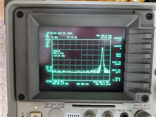
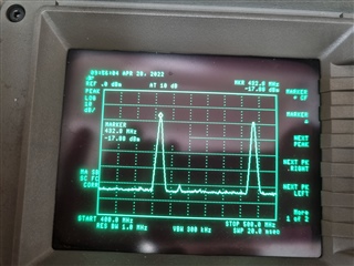
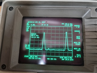

We checked TEST registers before via our FW.
Is it possible to change TEST registers via SmartRF?
I was referring to when you use SmartRF Studio for your test.
You can read what the registers are set to if you do a refresh (should not be required)

But: 486 MHz is outside the frequency band the chip support which indicate that the PLL is out of lock/ set the frequency to max. That normally means that the PLL is out of lock.
1) First transmit was in correct frequency (434MHz).
2) Second run transmit was around 486MHz instead of 434 (see attached picture <486.jpg>)
Could you outline in detail what/ where/ write in SmartRF Studio to regenerate this?