


Other Parts Discussed in Thread: AFE7920
Hi Team,
I noticed recently that on the TI secure folder are a couple of excel documents about AFE79xx matching networks, suggesting what kind of changes one should do to improve operation at higher frequency ranges (higher than 2.6 and 3.5 GHz). We followed those suggestions in order to improve operation at 8212.5 MHz and 6812.5 MHz by modifying the AFE7920EVM DACs C and D matching networks for TI-suggested ranges at 8.1 and 7.1 GHz, respectively.
However, a few things popped up with these modifications, namely:
1) the TI-suggested balun (Minicircuits NCR2-123+) has a bit larger footprint than what AFE7920EVM supports
2) we saw significant power loss at 6812.5 MHz for a network TI suggested at 7.1 GHz and also large loss at 8212.5 MHz on the network TI suggested for 8.1 GHz. See figure below (measured on DACs C and D with sinewave input [0 dBm, 600 MHz] and by sweeping DAC NCO frequency, where rectangular patches denote area where we expected to find some gain).
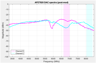
For the issue 2), just as a reference, we see about 10-15 dB of loss when integrating power over the patched areas when compared to measurements before any AFE7920EVM matching network changes.
My question for the TI team here is if you could help us understand what we can do to optimize the matching network for our application, as with current situation we have significant power losses which jeopardizes usage of AFE7920 within our project.
The scripts used for this test are identical to the ones from this post:
https://e2e.ti.com/support/rf-microwave-group/rf-microwave/f/rf-microwave-forum/1264375/afe7920evm-power-gain-in-analogue-repeater-configuration
Any subsequent (post-device bringup) changes to the NCO DAC frequency were done via AFE79xx GUI command window, so no special script was used for this.
Kind regards,
Željko
