This thread has been locked.

If you have a related question, please click the "Ask a related question" button in the top right corner. The newly created question will be automatically linked to this question.

AFE7799: Rx EVM% Improvement [AL]

Part Number: AFE7799
Other Parts Discussed in Thread: AFE7769, AFE7769EVM, TSW14J58EVM

Hi expert,

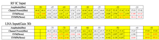
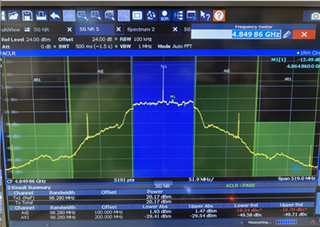
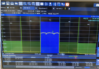
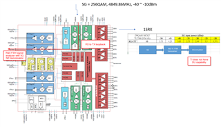
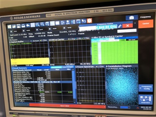
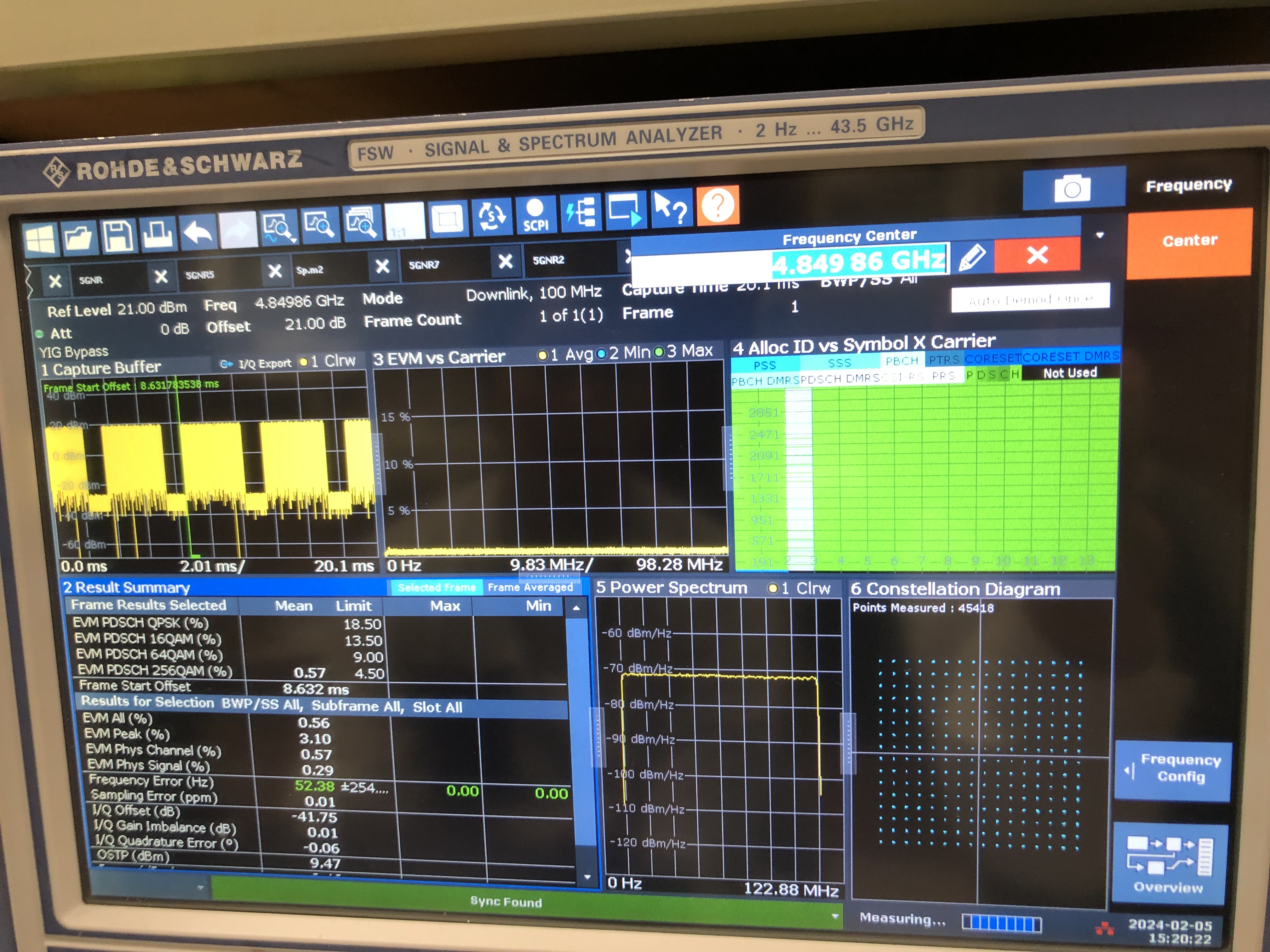
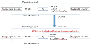
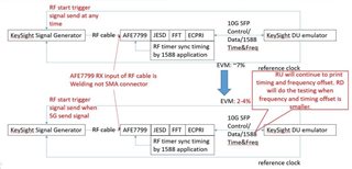
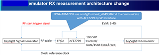
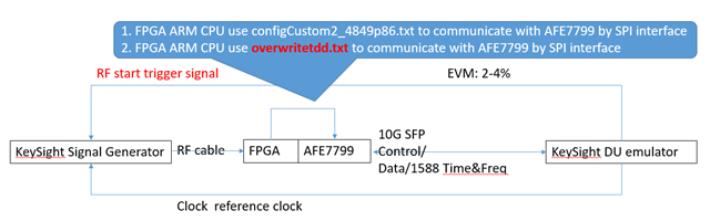
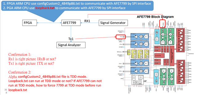
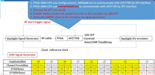
Customer measured Rx EVM of AFE7799 on their board and got over 2.5%. Would you please advise possible methods to improve Rx EVM?  

256QAM
TI EVM (%)

SG input power (dBm)

-50

-45

-40

-35

-30

-25

-20


RXATT

10

5.75

4.23

3.05

2.75

2.49

3.3

3.371


Thanks,

Allan

  • Hi expert,

    May I have your help to provide some insight how to improve Rx EVM?

    Thanks,

    Allan

  • Hi Allan,

    Please advise the exact test setup and block diagram. Please advise the SG model number.

    Please ask customer to plug in the SG directly into the spectrum analyzer 256QAM analysis to see the raw EVM% measured and compare against the AFE7799 raw EVM% performance. Thank you

    -Kang

  • Hi Kang,

    Please see below comments;

    1. Using N7631C signal studio to gen 245QAM signal file to SG and DU emulator.
    2. Connect EXG, AIO RU(TI7799 input), and DU emulator as block diagram.
    3. Analysis DU emulator output data by VSA, and get EVM performance.

    Thanks,

    Allan

  • Hello Allan,

    A few ideas:

    1. To double check if the image (sideband) and LO leakage impacts the performance, please ask customer to move the carrier away from the LO. If it is 20MHz bandwidth signal, please move the signal to the right by 10MHz so the edge of the carrier is at the LO. This will eliminate sideband and LO impacting the EVM%.
    2.  If this is a TDD system, please ask customer to enable the RXTDD pin to logic HI some time before the RX data starts. The RXTDD enable will power-up the analog circuitry and ensure settling of the RX circuits before the transmission of the RX data.
      1. NOTE: The RXTDD signal is used to turn on/off the RX circuitry for power consumption saving in TDD mode. The settling time has a typical maximum value of 2us. Therefore, please enable the RXTDD signal at least 2us ahead of the data decoding.
  • Customer to please advise the two actions above

    1. To double check if the image (sideband) and LO leakage impacts the performance, please ask customer to move the carrier away from the LO. If it is 20MHz bandwidth signal, please move the signal to the right by 10MHz so the edge of the carrier is at the LO. This will eliminate sideband and LO impacting the EVM%.
    2.  If this is a TDD system, please ask customer to enable the RXTDD pin to logic HI some time before the RX data starts. The RXTDD enable will power-up the analog circuitry and ensure settling of the RX circuits before the transmission of the RX data.
      1. NOTE: The RXTDD signal is used to turn on/off the RX circuitry for power consumption saving in TDD mode. The settling time has a typical maximum value of 2us. Therefore, please enable the RXTDD signal at least 2us ahead of the data decoding.

    Per our discussion, we will do the following:

    1. Modify AFE7769 EVM with 4.9GHz RX and TX RF front end matching
    2. Boot-up the AFE7769 EVM with configCustom2_4849.86 configuration text file
      1. configCustom2_4849p86.txt
    3. Enable loopback mode for RX to TX loopback
      1. Loopback script:
      2. Fullscreen
        1
        2
        3
        4
        5
        6
        7
        8
        9
        10
        11
        12
        13
        14
        15
        16
        17
        18
        19
        20
        21
        def synch(val):
        device.JESD.ADC_TX[0].ADC_TX.JESD_TX_CONFIG83.sync_override=12
        device.JESD.ADC_TX[0].ADC_TX.JESD_TX_CONFIG83.sync=12*val
        device.JESD.ADC_TX[1].ADC_TX.JESD_TX_CONFIG83.sync_override=12
        device.JESD.ADC_TX[1].ADC_TX.JESD_TX_CONFIG83.sync=12*val
        device.hardReadAlways=True
        device.currentPageSelected.setValue(0)
        device.logEn=1
        device.JESD.SUBCHIP.SUBCHIP.JESD_SUBCHIP_REG72.loop_back_mode_tx1=1 # 0
        device.JESD.SUBCHIP.SUBCHIP.JESD_SUBCHIP_REG72.loop_back_mode_tx0=1
        device.JESD.SUBCHIP.SUBCHIP.JESD_SUBCHIP_REG73.serdes_fifo_read_dly=1
        device.JESD.SUBCHIP.SUBCHIP.JESD_SUBCHIP_REG73.loop_back_fifo_init_state=1
        device.JESD.SUBCHIP.SUBCHIP.JESD_SUBCHIP_REG73.loop_back_fifo_init_state=0
        for chNo in range(2):
        for offset in range(4):
        device.JESD.SERDES[chNo].laneRegisters[offset].TIMING_PHASE12_OVERWRITE.OWEN_PHASE1_ACC=1
        XXXXXXXXXXXXXXXXXXXXXXXXXXXXXXXXXXXXXXXXXXXXXXXXXX
    4. Inject TM3.1A 256QAM DL signal into the RX port, measure at the TX port with SA to demodulate EVM%
    5. Look for ways to optimize the configuration.


    Thank you.

  • Hi Kang,

    Customer originally use -50Mhz to -30Mhz bandwidth from LO and now move to -40Mhz to -20Mhz. The EVM improved from -7% to -2%.

    They are still doing test to enable RXTDD 2us before Rx.

    In the meantime, customer also tried to use loopback followed your steps. Some questions,

    Q1. how to boot up the AFE7769EVM using the configCustom2_4849.86 configuration text file in Latte? 

    1. configCustom2_4849p86.txt

    Customer add loopback script directly into Latte, and show errors and sync failed.

    Q2: please advise what might goes wrong when customer implement the loopback script? 

    Here is the test setup and result by plugging SG directly into the spectrum analyzer 256QAM analysis to see the raw EVM%.

    Q3: customer is TDD system, but for loopback, want to clarify shall we use FDD instead?

    Thanks,

    Allan

  • Hi Allan,

    Please advise which plot is below: is it loopback or is it directly captured from the RX? The EVM% is very good and less than 2%. We would like to double check how did the customer arrive to this?

    Regarding your other questions:

    Customer originally use -50Mhz to -30Mhz bandwidth from LO and now move to -40Mhz to -20Mhz. The EVM improved from -7% to -2%.

    Could the customer please double check if the RX interface rate is currently set to 122.88MSPS. If the interface rate is at 122.88MSPS, the DDC bandwidth is only 100MHz (i.e. 122.88MSPS*80%). Therefore, the utilization of the -50MHz at the band edge may be pushing towards the edge of the DDC filter.

    They are still doing test to enable RXTDD 2us before Rx.

    For now, please ensure RXTDD pin is always in logic HI in FDD mode so we can have the RX signal chain enabled all the time. This will prevent additional variable introduced to the EVM% from the RX signal chain switching characteristics.

    Q1. how to boot up the AFE7769EVM using the configCustom2_4849.86 configuration text file in Latte? 

    1. configCustom2_4849p86.txt

    We are currently looking into a native boot of the configuration file sequence for you. We will upload the code once we find it.

    Q2: please advise what might goes wrong when customer implement the loopback script? 

    Here is the test setup and result by plugging SG directly into the spectrum analyzer 256QAM analysis to see the raw EVM%.

    We are still working on this and will get back to you.

    Q3: customer is TDD system, but for loopback, want to clarify shall we use FDD instead?

    Please keep  RXTDD pin is always in logic HI in FDD mode for now to prevent additional transient variables. 

  • Hi Kang,

    The 0.57% EVM is just a directly captured from the RX as a good reference to approve the Rx signal is good. 

    RX interface rate is set to 122.88MSPS.

    One thing want to correct is the test did yesterday the EVM improved from -7% to -2% only happened once. 

    Customer did some further different tests shifting the carrier but don't see EVM much different. 

    p.s. SG to AFE7799 Rx and RxTDD set to 10dB. 

    1. Start PRB0 and RXTDD is TDD mode

    2. Start PRB0 and RXTDD is always On in FDD mode.

    3. Start PRB25 and RXTDD is TDD mode

    4. Start PRB111 and RXTDD is TDD mode

    Also wondering, is there any possible HW design e.g. power, clocks may impact the Rx EVM as well? If so, could you please point out something for customer to check? 

    Regards,

    Allan

  • One thing want to correct is the test did yesterday the EVM improved from -7% to -2% only happened once. 

    Allan,

    Please advise ask the customer to backtrack the steps done to get to 2% EVM%

  • Kang,

    Customer clarified the test history. EVM was good by changing the RF start trigger timing from 1588 application to DU emulator 1pps signal. But the EVM 2% was the best case and hard to duplicate at the same environment.

    p.s. in the previous tests that SG to AFE7799 Rx and RxTDD set to 10dB. 

    Thanks,
    Allan

  • Kang,

    Some further comments from customer below. 

    I don’t think it is LO leakage issue, because you can see I/Q offset value already low to -45dB.


    Normally, EVM contributes factor are: non-linearity, LO leakage (I/Q offset), image signal (I/Q imbalance), phase noise and noise floor.


    I guess it is noise floor issue by DDC setting.

    If DDC (digital down convert) setting not good, the noise will into in band signal. You can check test figure, some spurious is very close wanted signal.


    Non-linearity: already had did all range of RX input power

    LO leakage: from test result table, <-45dB

    Phase noise: TX EVM already be proved by TX chain (5W RU TX EVM can <2%)

    Image rejection: i believe QEC already default be enabled 

    Regards,

    Allan

  • Hi Allan,

    could you please advise how the 1pps signal is connected to the AFE7799? This will help provide some insight on improving the EVM% measurement. 

    By changing RF start trigger timing from 1588 application to 1pps signal, I believe only the demodulation frame start changes (i.e. on the DU emulator timing). I do not think any AFE7799 hardware connection and software had been changed. Please advise. 

  • Hi Allen,

    Can you please advise the customer the following steps for the loopback mode?

    1) Bringup the EVM with the below script. For loopback mode, LMFS should be same thus we modified a script and attached below. sysParams.syncLoopBack  should be False to ensure the link for EVM testing. 

    1
    2
    3
    4
    5
    6
    7
    8
    9
    10
    11
    12
    13
    14
    15
    16
    17
    18
    19
    '''
    Case RX TX FB CLK Notes
    ---- ----------------- ----------------- ----------------- ----------- ------------
    2 245.76Msps, 24410 245.76Msps, 24410 245.76Msps, 12410 FS=2949.12M
    SerDes=9830.4Mbps SerDes=9830.4Mbps SerDes=9830.4Mbps REF=491.52M
    PLL0, LO=3500M PLL0, LO=3500M NCO=3500M
    '''
    sysParams.__init__() #Resets sysParams settings to default values set in "mAfeParameters.py"
    setupParams.selectedDut=1
    if boardType in ("EVM","HSC1373"):
    if setupParams.selectedDut==1:
    AFE=AFE1
    device=device1
    logDumpInst=logDumpInst1
    else:
    AFE=AFE0
    device=device0
    logDumpInst=logDumpInst0
    XXXXXXXXXXXXXXXXXXXXXXXXXXXXXXXXXXXXXXXXXXXXXXXXXX

    2) Run the below script for the Rx->Tx loopback. If any link issue happens, please try calling AFE.adcDacSync(1)

    1
    2
    3
    4
    5
    6
    7
    8
    9
    10
    11
    12
    13
    14
    15
    16
    17
    18
    19
    def synch(val):
    device.JESD.ADC_TX[0].ADC_TX.JESD_TX_CONFIG83.sync_override=12
    device.JESD.ADC_TX[0].ADC_TX.JESD_TX_CONFIG83.sync=12*val
    device.JESD.ADC_TX[1].ADC_TX.JESD_TX_CONFIG83.sync_override=12
    device.JESD.ADC_TX[1].ADC_TX.JESD_TX_CONFIG83.sync=12*val
    device.hardReadAlways=True
    device.currentPageSelected.setValue(0)
    device.logEn=1
    device.JESD.SUBCHIP.SUBCHIP.JESD_SUBCHIP_REG72.loop_back_mode_tx1=1 # 0
    device.JESD.SUBCHIP.SUBCHIP.JESD_SUBCHIP_REG72.loop_back_mode_tx0=1
    device.JESD.SUBCHIP.SUBCHIP.JESD_SUBCHIP_REG73.serdes_fifo_read_dly=1
    device.JESD.SUBCHIP.SUBCHIP.JESD_SUBCHIP_REG73.loop_back_fifo_init_state=1
    device.JESD.SUBCHIP.SUBCHIP.JESD_SUBCHIP_REG73.loop_back_fifo_init_state=0
    for chNo in range(2):
    for offset in range(4):
    XXXXXXXXXXXXXXXXXXXXXXXXXXXXXXXXXXXXXXXXXXXXXXXXXX

    3) Select the proper channels, for Rx and Tx. In our case we used Rx1->Tx1. Therefore, 

    AFE.selectCh(0,0)
    AFE.selectCh(2,0)

    4) Observe the signal on VSA.

    Please let us know about the outcome of this experiment.

    Thanks,

    Serkan

  • Hi Kang,

    could you please advise how the 1pps signal is connected to the AFE7799?

    After clarifying, please see updated test setup, 

    Regards,

    Allan

  • Dear Kang:

        Today we test Alpha_EVM_bringup.py and loopback.py at two kinds of HW platform. Alpha_EVM_bringup.py has “AttributeError: 'NoneType' object has no attribute 'Reconnect'” issue. And loopback.py happen may serdes sync error. Please check with internal team and give us suggestions. Thanks a lot.


    1. TI 7769EVB + TI FPGA board. Test results are on the below.
      • py

    #Executing .. Files/TI_0210/Alpha_EVM_bringup.py

    #Start Time 2024-02-12 15:29:14.432000

    DONOT_OPEN_Afe77xxPG1p1_FULL - Device registers reset.

    chipType: 0xa

    chipId: 0x77

    chipVersion: 0x11

    2T2R1F Number: 0

    Valid Configuration: True

    laneRateRx: 4915.2

    laneRateFb: 4915.2

    laneRateTx: 4915.2

    2T2R1F Number: 1

    Valid Configuration: True

    laneRateRx: 4915.2

    laneRateFb: 4915.2

    laneRateTx: 4915.2

    Resetting FPGA.

    #Error: 'NoneType' object has no attribute 'Reconnect'

    # "Files/TI_0210/Alpha_EVM_bringup.py", line 203, in

    # File "C:\Users\Michael Jang\Documents\Texas Instruments\Latte\lib\\Afe77xxLibraries\\AFE77xxLibraryPG1P1\mFuncDecorator.py", line 101, in inDecorator

    # a=func(*args)

    # File "C:\Users\Michael Jang\Documents\Texas Instruments\Latte\lib\\Afe77xxLibraries\\AFE77xxLibraryPG1P1\mAfeLibrary.py", line 216, in deviceBringup

    # self.FPGA.reset()

    # File "C:\Users\Michael Jang\Documents\Texas Instruments\Latte\lib\\Afe77xxLibraries\\AFE77xxLibraryPG1P1\mFuncDecorator.py", line 101, in inDecorator

    # a=func(*args)

    # File "C:\Users\Michael Jang\Documents\Texas Instruments\Latte\lib\\Afe77xxLibraries\\AFE77xxLibraryPG1P1\mFPGA_J58.py", line 51, in reset

    # r = self.regs.Reconnect()

    # AttributeError: 'NoneType' object has no attribute 'Reconnect'

    #

    #

    #Done executing .. Files/TI_0210/Alpha_EVM_bringup.py

    #End Time 2024-02-12 15:29:15.950000

    #Execution Time = 1.51800012589 s

    #================ ERRORS:1, WARNINGS:0 ================#


    • py

    #======

    #Executing .. Files/TI_0210/loopback.py

    #Start Time 2024-02-12 15:30:19.383000

    device.writeReg(0x15,0x08)

    device.readReg(0x0000004B,0x00000032)

    device.readReg(0x0000004A,0x00000010)

    device.readReg(0x00000048,0x00000000)

    device.writeReg(0x48,0x04)

    device.readReg(0x0000004B,0x00000032)

    device.readReg(0x0000004A,0x00000010)

    device.readReg(0x00000048,0x00000004)

    device.writeReg(0x48,0x05)

    device.readReg(0x0000004B,0x00000032)

    device.readReg(0x0000004A,0x00000010)

    device.readReg(0x00000049,0x00000001)

    device.writeReg(0x49,0x03)

    device.readReg(0x0000004B,0x00000032)

    device.readReg(0x0000004A,0x00000010)

    device.readReg(0x00000049,0x00000003)

    device.writeReg(0x49,0x03)

    device.readReg(0x0000004B,0x00000032)

    device.readReg(0x0000004A,0x00000010)

    device.readReg(0x00000049,0x00000003)

    device.writeReg(0x49,0x02)

    device.writeReg(0x15,0x00)

    device.writeReg(0x15,0x04)

    device.writeReg(0x15,0x04)

    device.writeReg(0x15,0x00)

    device.writeReg(0x15,0x00)

    device.writeReg(0x15,0x08)

    device.readReg(0x00000021,0x00000012)

    device.readReg(0x00004687,0x00000000)

    device.readReg(0x00004687,0x00000000)

    device.readReg(0x00004686,0x00000000)

    device.readReg(0x00004686,0x00000000)

    device.writeReg(0x4687,0x80)

    device.writeReg(0x4686,0x00)

    device.writeReg(0x15,0x00)

    device.writeReg(0x15,0x04)

    device.writeReg(0x15,0x04)

    device.writeReg(0x15,0x00)

    device.writeReg(0x15,0x00)

    device.writeReg(0x15,0x08)

    device.readReg(0x00000021,0x00000012)

    device.readReg(0x00004487,0x00000080)

    device.readReg(0x00004487,0x00000080)

    device.readReg(0x00004486,0x00000000)

    device.readReg(0x00004486,0x00000000)

    device.writeReg(0x4487,0x80)

    device.writeReg(0x4486,0x00)

    device.writeReg(0x15,0x00)

    device.writeReg(0x15,0x04)

    device.writeReg(0x15,0x04)

    device.writeReg(0x15,0x00)

    device.writeReg(0x15,0x00)

    device.writeReg(0x15,0x08)

    device.readReg(0x00000021,0x00000012)

    device.readReg(0x00004087,0x00000080)

    device.readReg(0x00004087,0x00000080)

    device.readReg(0x00004086,0x00000000)

    device.readReg(0x00004086,0x00000000)

    device.writeReg(0x4087,0x80)

    device.writeReg(0x4086,0x00)

    device.writeReg(0x15,0x00)

    device.writeReg(0x15,0x04)

    device.writeReg(0x15,0x04)

    device.writeReg(0x15,0x00)

    device.writeReg(0x15,0x00)

    device.writeReg(0x15,0x08)

    device.readReg(0x00000021,0x00000012)

    device.readReg(0x00004287,0x00000080)

    device.readReg(0x00004287,0x00000080)

    device.readReg(0x00004286,0x00000000)

    device.readReg(0x00004286,0x00000000)

    device.writeReg(0x4287,0x80)

    device.writeReg(0x4286,0x00)

    device.writeReg(0x15,0x00)

    device.writeReg(0x15,0x00)

    device.writeReg(0x15,0x40)

    device.writeReg(0x15,0x40)

    device.writeReg(0x15,0x00)

    device.writeReg(0x15,0x08)

    device.readReg(0x00000022,0x00000012)

    device.readReg(0x00004287,0x00000080)

    device.readReg(0x00004287,0x00000080)

    device.readReg(0x00004286,0x00000000)

    device.readReg(0x00004286,0x00000000)

    device.writeReg(0x4287,0x80)

    device.writeReg(0x4286,0x00)

    device.writeReg(0x15,0x00)

    device.writeReg(0x15,0x00)

    device.writeReg(0x15,0x40)

    device.writeReg(0x15,0x40)

    device.writeReg(0x15,0x00)

    device.writeReg(0x15,0x08)

    device.readReg(0x00000022,0x00000012)

    device.readReg(0x00004087,0x00000080)

    device.readReg(0x00004087,0x00000080)

    device.readReg(0x00004086,0x00000000)

    device.readReg(0x00004086,0x00000000)

    device.writeReg(0x4087,0x80)

    device.writeReg(0x4086,0x00)

    device.writeReg(0x15,0x00)

    device.writeReg(0x15,0x00)

    device.writeReg(0x15,0x40)

    device.writeReg(0x15,0x40)

    device.writeReg(0x15,0x00)

    device.writeReg(0x15,0x08)

    device.readReg(0x00000022,0x00000012)

    device.readReg(0x00004487,0x00000080)

    device.readReg(0x00004487,0x00000080)

    device.readReg(0x00004486,0x00000000)

    device.readReg(0x00004486,0x00000000)

    device.writeReg(0x4487,0x80)

    device.writeReg(0x4486,0x00)

    device.writeReg(0x15,0x00)

    device.writeReg(0x15,0x00)

    device.writeReg(0x15,0x40)

    device.writeReg(0x15,0x40)

    device.writeReg(0x15,0x00)

    device.writeReg(0x15,0x08)

    device.readReg(0x00000022,0x00000012)

    device.readReg(0x00004687,0x00000080)

    device.readReg(0x00004687,0x00000080)

    device.readReg(0x00004686,0x00000000)

    device.readReg(0x00004686,0x00000000)

    device.writeReg(0x4687,0x80)

    device.writeReg(0x4686,0x00)

    device.writeReg(0x15,0x00)

    device.writeReg(0x15,0x01)

    device.writeReg(0x15,0x01)

    device.readReg(0x00000073,0x00000000)

    device.readReg(0x00000072,0x00000000)

    device.writeReg(0x72,0xC0)

    device.readReg(0x00000073,0x00000000)

    device.readReg(0x00000072,0x000000C0)

    device.writeReg(0x72,0xCC)

    device.writeReg(0x15,0x00)

    device.writeReg(0x15,0x10)

    device.readReg(0x00000073,0x00000000)

    device.readReg(0x00000072,0x00000000)

    device.writeReg(0x72,0xC0)

    device.readReg(0x00000073,0x00000000)

    device.readReg(0x00000072,0x000000C0)

    device.writeReg(0x72,0xCC)

    device.writeReg(0x15,0x11)

    device.writeReg(0x15,0x01)

    device.readReg(0x00000073,0x00000000)

    device.readReg(0x00000072,0x000000CC)

    device.writeReg(0x72,0xCC)

    device.readReg(0x00000073,0x00000000)

    device.readReg(0x00000072,0x000000CC)

    device.writeReg(0x72,0xC0)

    device.writeReg(0x15,0x00)

    device.writeReg(0x15,0x10)

    device.readReg(0x00000073,0x00000000)

    device.readReg(0x00000072,0x000000CC)

    device.writeReg(0x72,0xCC)

    device.readReg(0x00000073,0x00000000)

    device.readReg(0x00000072,0x000000CC)

    device.writeReg(0x72,0xC0)

    device.writeReg(0x15,0x10)

    device.writeReg(0x15,0x00)

    ###########Device DAC JESD-RX 0 Link Status###########

    LOS Indicator for (Serdes Loss of signal) lane 0: 1

    Frame Sync error (unexpected k28.5) for lane 0: 0

    LOS Indicator for (Serdes Loss of signal) lane 1: 1

    Frame Sync error (unexpected k28.5) for lane 1: 0

    LOS Indicator for (Serdes Loss of signal) lane 2: 1

    Frame Sync error (unexpected k28.5) for lane 2: 0

    LOS Indicator for (Serdes Loss of signal) lane 3: 1

    Frame Sync error (unexpected k28.5) for lane 3: 0

    Comma Align Lock Lane0: False; Please check if the transmitter is sending data and eye is good.

    Comma Align Lock Lane1: False; Please check if the transmitter is sending data and eye is good.

    CS State TX0: 0b00000000 . It is expected to be 0b00001010

    FS State TX0: 0b00000000 . It is expected to be 0b00000101

    Couldn't get the link up for device RX: 0; Alarms: 0xf00

    ###################################

    ###########Device DAC JESD-RX 1 Link Status###########

    LOS Indicator for (Serdes Loss of signal) lane 0: 1

    Frame Sync error (unexpected k28.5) for lane 0: 0

    LOS Indicator for (Serdes Loss of signal) lane 1: 1

    Frame Sync error (unexpected k28.5) for lane 1: 0

    LOS Indicator for (Serdes Loss of signal) lane 2: 1

    Frame Sync error (unexpected k28.5) for lane 2: 0

    LOS Indicator for (Serdes Loss of signal) lane 3: 1

    Frame Sync error (unexpected k28.5) for lane 3: 0

    Comma Align Lock Lane0: False; Please check if the transmitter is sending data and eye is good.

    Comma Align Lock Lane1: False; Please check if the transmitter is sending data and eye is good.

    CS State TX0: 0b00000000 . It is expected to be 0b00001010

    FS State TX0: 0b00000000 . It is expected to be 0b00000101

    Couldn't get the link up for device RX: 1; Alarms: 0xf00

    ###################################

    #Done executing .. Files/TI_0210/loopback.py

    #End Time 2024-02-12 15:30:39.292000

    #Execution Time = 19.9090001583 s

    #================ ERRORS:22, WARNINGS:0 ================#


    1. TI 7769EVB + Alpha FPGA board.
      • 1 Alpha_EVM_bringup.py

    #======

    #Executing .. Files/TI_0210/Alpha_EVM_bringup.py

    #Start Time 2024-02-12 14:59:18.753000

    DONOT_OPEN_Afe77xxPG1p1_FULL - Device registers reset.

    chipType: 0xa

    chipId: 0x77

    chipVersion: 0x11

    2T2R1F Number: 0

    Valid Configuration: True

    laneRateRx: 4915.2

    laneRateFb: 4915.2

    laneRateTx: 4915.2

    2T2R1F Number: 1

    Valid Configuration: True

    laneRateRx: 4915.2

    laneRateFb: 4915.2

    laneRateTx: 4915.2

    Resetting FPGA.

    #Error: 'NoneType' object has no attribute 'Reconnect'

    # "Files/TI_0210/Alpha_EVM_bringup.py", line 203, in

    # File "C:\Users\Michael Jang\Documents\Texas Instruments\Latte\lib\\Afe77xxLibraries\\AFE77xxLibraryPG1P1\mFuncDecorator.py", line 101, in inDecorator

    # a=func(*args)

    # File "C:\Users\Michael Jang\Documents\Texas Instruments\Latte\lib\\Afe77xxLibraries\\AFE77xxLibraryPG1P1\mAfeLibrary.py", line 216, in deviceBringup

    # self.FPGA.reset()

    # File "C:\Users\Michael Jang\Documents\Texas Instruments\Latte\lib\\Afe77xxLibraries\\AFE77xxLibraryPG1P1\mFuncDecorator.py", line 101, in inDecorator

    # a=func(*args)

    # File "C:\Users\Michael Jang\Documents\Texas Instruments\Latte\lib\\Afe77xxLibraries\\AFE77xxLibraryPG1P1\mFPGA_J58.py", line 51, in reset

    # r = self.regs.Reconnect()

    # AttributeError: 'NoneType' object has no attribute 'Reconnect'

    #

    #

    #Done executing .. Files/TI_0210/Alpha_EVM_bringup.py

    #End Time 2024-02-12 14:59:20.456000

    #Execution Time = 1.70300006866 s

    #================ ERRORS:1, WARNINGS:0 ================#


    • py

    #======

    #Executing .. Files/TI_0210/loopback.py

    #Start Time 2024-02-12 15:00:14.651000

    device.writeReg(0x15,0x08)

    device.readReg(0x0000004B,0x00000032)

    device.readReg(0x0000004A,0x00000010)

    device.readReg(0x00000048,0x00000000)

    device.writeReg(0x48,0x04)

    device.readReg(0x0000004B,0x00000032)

    device.readReg(0x0000004A,0x00000010)

    device.readReg(0x00000048,0x00000004)

    device.writeReg(0x48,0x05)

    device.readReg(0x0000004B,0x00000032)

    device.readReg(0x0000004A,0x00000010)

    device.readReg(0x00000049,0x00000001)

    device.writeReg(0x49,0x03)

    device.readReg(0x0000004B,0x00000032)

    device.readReg(0x0000004A,0x00000010)

    device.readReg(0x00000049,0x00000003)

    device.writeReg(0x49,0x03)

    device.readReg(0x0000004B,0x00000032)

    device.readReg(0x0000004A,0x00000010)

    device.readReg(0x00000049,0x00000003)

    device.writeReg(0x49,0x02)

    device.writeReg(0x15,0x00)

    device.writeReg(0x15,0x04)

    device.writeReg(0x15,0x04)

    device.writeReg(0x15,0x00)

    device.writeReg(0x15,0x00)

    device.writeReg(0x15,0x08)

    device.readReg(0x00000021,0x00000012)

    device.readReg(0x00004687,0x00000000)

    device.readReg(0x00004687,0x00000000)

    device.readReg(0x00004686,0x00000000)

    device.readReg(0x00004686,0x00000000)

    device.writeReg(0x4687,0x80)

    device.writeReg(0x4686,0x00)

    device.writeReg(0x15,0x00)

    device.writeReg(0x15,0x04)

    device.writeReg(0x15,0x04)

    device.writeReg(0x15,0x00)

    device.writeReg(0x15,0x00)

    device.writeReg(0x15,0x08)

    device.readReg(0x00000021,0x00000012)

    device.readReg(0x00004487,0x00000080)

    device.readReg(0x00004487,0x00000080)

    device.readReg(0x00004486,0x00000000)

    device.readReg(0x00004486,0x00000000)

    device.writeReg(0x4487,0x80)

    device.writeReg(0x4486,0x00)

    device.writeReg(0x15,0x00)

    device.writeReg(0x15,0x04)

    device.writeReg(0x15,0x04)

    device.writeReg(0x15,0x00)

    device.writeReg(0x15,0x00)

    device.writeReg(0x15,0x08)

    device.readReg(0x00000021,0x00000012)

    device.readReg(0x00004087,0x00000080)

    device.readReg(0x00004087,0x00000080)

    device.readReg(0x00004086,0x00000000)

    device.readReg(0x00004086,0x00000000)

    device.writeReg(0x4087,0x80)

    device.writeReg(0x4086,0x00)

    device.writeReg(0x15,0x00)

    device.writeReg(0x15,0x04)

    device.writeReg(0x15,0x04)

    device.writeReg(0x15,0x00)

    device.writeReg(0x15,0x00)

    device.writeReg(0x15,0x08)

    device.readReg(0x00000021,0x00000012)

    device.readReg(0x00004287,0x00000080)

    device.readReg(0x00004287,0x00000080)

    device.readReg(0x00004286,0x00000000)

    device.readReg(0x00004286,0x00000000)

    device.writeReg(0x4287,0x80)

    device.writeReg(0x4286,0x00)

    device.writeReg(0x15,0x00)

    device.writeReg(0x15,0x00)

    device.writeReg(0x15,0x40)

    device.writeReg(0x15,0x40)

    device.writeReg(0x15,0x00)

    device.writeReg(0x15,0x08)

    device.readReg(0x00000022,0x00000012)

    device.readReg(0x00004287,0x00000080)

    device.readReg(0x00004287,0x00000080)

    device.readReg(0x00004286,0x00000000)

    device.readReg(0x00004286,0x00000000)

    device.writeReg(0x4287,0x80)

    device.writeReg(0x4286,0x00)

    device.writeReg(0x15,0x00)

    device.writeReg(0x15,0x00)

    device.writeReg(0x15,0x40)

    device.writeReg(0x15,0x40)

    device.writeReg(0x15,0x00)

    device.writeReg(0x15,0x08)

    device.readReg(0x00000022,0x00000012)

    device.readReg(0x00004087,0x00000080)

    device.readReg(0x00004087,0x00000080)

    device.readReg(0x00004086,0x00000000)

    device.readReg(0x00004086,0x00000000)

    device.writeReg(0x4087,0x80)

    device.writeReg(0x4086,0x00)

    device.writeReg(0x15,0x00)

    device.writeReg(0x15,0x00)

    device.writeReg(0x15,0x40)

    device.writeReg(0x15,0x40)

    device.writeReg(0x15,0x00)

    device.writeReg(0x15,0x08)

    device.readReg(0x00000022,0x00000012)

    device.readReg(0x00004487,0x00000080)

    device.readReg(0x00004487,0x00000080)

    device.readReg(0x00004486,0x00000000)

    device.readReg(0x00004486,0x00000000)

    device.writeReg(0x4487,0x80)

    device.writeReg(0x4486,0x00)

    device.writeReg(0x15,0x00)

    device.writeReg(0x15,0x00)

    device.writeReg(0x15,0x40)

    device.writeReg(0x15,0x40)

    device.writeReg(0x15,0x00)

    device.writeReg(0x15,0x08)

    device.readReg(0x00000022,0x00000012)

    device.readReg(0x00004687,0x00000080)

    device.readReg(0x00004687,0x00000080)

    device.readReg(0x00004686,0x00000000)

    device.readReg(0x00004686,0x00000000)

    device.writeReg(0x4687,0x80)

    device.writeReg(0x4686,0x00)

    device.writeReg(0x15,0x00)

    device.writeReg(0x15,0x01)

    device.writeReg(0x15,0x01)

    device.readReg(0x00000073,0x00000000)

    device.readReg(0x00000072,0x00000000)

    device.writeReg(0x72,0xC0)

    device.readReg(0x00000073,0x00000000)

    device.readReg(0x00000072,0x000000C0)

    device.writeReg(0x72,0xCC)

    device.writeReg(0x15,0x00)

    device.writeReg(0x15,0x10)

    device.readReg(0x00000073,0x00000000)

    device.readReg(0x00000072,0x00000000)

    device.writeReg(0x72,0xC0)

    device.readReg(0x00000073,0x00000000)

    device.readReg(0x00000072,0x000000C0)

    device.writeReg(0x72,0xCC)

    device.writeReg(0x15,0x11)

    device.writeReg(0x15,0x01)

    device.readReg(0x00000073,0x00000000)

    device.readReg(0x00000072,0x000000CC)

    device.writeReg(0x72,0xCC)

    device.readReg(0x00000073,0x00000000)

    device.readReg(0x00000072,0x000000CC)

    device.writeReg(0x72,0xC0)

    device.writeReg(0x15,0x00)

    device.writeReg(0x15,0x10)

    device.readReg(0x00000073,0x00000000)

    device.readReg(0x00000072,0x000000CC)

    device.writeReg(0x72,0xCC)

    device.readReg(0x00000073,0x00000000)

    device.readReg(0x00000072,0x000000CC)

    device.writeReg(0x72,0xC0)

    device.writeReg(0x15,0x10)

    device.writeReg(0x15,0x00)

    ###########Device DAC JESD-RX 0 Link Status###########

    LOS Indicator for (Serdes Loss of signal) lane 0: 1

    Frame Sync error (unexpected k28.5) for lane 0: 0

    LOS Indicator for (Serdes Loss of signal) lane 1: 1

    Frame Sync error (unexpected k28.5) for lane 1: 0

    LOS Indicator for (Serdes Loss of signal) lane 2: 1

    Frame Sync error (unexpected k28.5) for lane 2: 0

    LOS Indicator for (Serdes Loss of signal) lane 3: 1

    Frame Sync error (unexpected k28.5) for lane 3: 0

    Comma Align Lock Lane0: False; Please check if the transmitter is sending data and eye is good.

    Comma Align Lock Lane1: False; Please check if the transmitter is sending data and eye is good.

    CS State TX0: 0b00000000 . It is expected to be 0b00001010

    FS State TX0: 0b00000000 . It is expected to be 0b00000101

    Couldn't get the link up for device RX: 0; Alarms: 0xf00

    ###################################

    ###########Device DAC JESD-RX 1 Link Status###########

    LOS Indicator for (Serdes Loss of signal) lane 0: 1

    Frame Sync error (unexpected k28.5) for lane 0: 0

    LOS Indicator for (Serdes Loss of signal) lane 1: 1

    Frame Sync error (unexpected k28.5) for lane 1: 0

    LOS Indicator for (Serdes Loss of signal) lane 2: 1

    Frame Sync error (unexpected k28.5) for lane 2: 0

    LOS Indicator for (Serdes Loss of signal) lane 3: 1

    Frame Sync error (unexpected k28.5) for lane 3: 0

    Comma Align Lock Lane0: False; Please check if the transmitter is sending data and eye is good.

    Comma Align Lock Lane1: False; Please check if the transmitter is sending data and eye is good.

    CS State TX0: 0b00000000 . It is expected to be 0b00001010

    FS State TX0: 0b00000000 . It is expected to be 0b00000101

    Couldn't get the link up for device RX: 1; Alarms: 0xf00

    ###################################

    #Done executing .. Files/TI_0210/loopback.py

    #End Time 2024-02-12 15:00:35.113000

    #Execution Time = 20.4619998932 s

    #================ ERRORS:22, WARNINGS:0 ================#


    Regards,

    TzuChung_Ke

  • Hi Allan,

    After clarifying, please see updated test setup, 

    In regards to the diagram above, from TI's perspective, we will need clarification on the RF timer sync timing by 1588 application to the RXTDD pins for TDD control.

    I would like to recommend Tzuchung to override the RXTDD to have the RX chain always enabled, as requested on Jan 29th, 2024. 

    Fullscreen
    1
    2
    3
    4
    5
    6
    7
    8
    9
    10
    11
    12
    13
    14
    15
    16
    17
    18
    19
    20
    21
    void overrideTdd(int fd,int overrideEn,int rxTdd,int fbTdd,int txTdd){
    /* overrideEn= 0:no override. control goes to pin, 1:TDD is forced acoording to rxTdd, fbTdd and txTdd.
    rxTdd=0:RX ABCD are off, 1:RX AB is on, 2:RX CD is on, 3:RX ABCD are on
    fbTdd=0:FB 1&2 are off, 1:FB 1 is on, 2:FB 2 is on, 3:FB 1&2 are on
    txTdd=0:TX ABCD are off, 1:TX AB is on, 2:TX CD is on, 3:TX ABCD are on
    */
    AFE77xx_RegWrite(fd,0x0014,0x04);
    AFE77xx_RegWrite(fd,0x124,overrideEn);
    AFE77xx_RegWrite(fd,0x126,overrideEn);
    AFE77xx_RegWrite(fd,0x128,overrideEn);
    AFE77xx_RegWrite(fd,0x12a,overrideEn);
    AFE77xx_RegWrite(fd,0x12c,overrideEn);
    AFE77xx_RegWrite(fd,0x12e,overrideEn);
    AFE77xx_RegWrite(fd,0x125,(overrideEn&(txTdd&1)));
    AFE77xx_RegWrite(fd,0x127,(overrideEn&(rxTdd&1)));
    AFE77xx_RegWrite(fd,0x129,(overrideEn&(fbTdd&1)));
    AFE77xx_RegWrite(fd,0x12b,(overrideEn&((txTdd&2)>>1)));
    AFE77xx_RegWrite(fd,0x12d,(overrideEn&((rxTdd&2)>>1)));
    AFE77xx_RegWrite(fd,0x12f,(overrideEn&((fbTdd&2)>>1)));
    AFE77xx_RegWrite(fd,0x0014,0x00);
    }
    XXXXXXXXXXXXXXXXXXXXXXXXXXXXXXXXXXXXXXXXXXXXXXXXXX

    Please use overrideTdd(int fd = 0, int overrideEN = 1, rxTdd = 3, fbtTdd = don't care, txTdd = don't care) function to always enable the RX chain. The impact from the RF timer sync timing by 1588 applications should no longer be a variable.

    Once the 1588 applications to the AFE7799 device RXTDD control is no longer a variable, please report back the EVM%. The best EVM% will be the current best theoretical EVM%.

    -Kang

  • Dear Kang:

    Question 1:

    We want to confirm configCustom2_4849p86.txt provided by us need to any modification or not for RX EVM improvement? Because all test and measurement depend on AFE7799 configuration is valid without error.

    Question 2:

    If we hope to use the “void overrideTdd” function to do the test, we must translate overrideTdd  function to txt mode.Beside we have done EVM measurement by FPGA always configure RXATT is High. So TI want to measure the EVM again by overrideTdd function again or not?

  • Dear Serkan:

    1. ALPHA_EVM_bringup.py has #Error: 'NoneType' object has no attribute 'Reconnect'. Can we ignore it?

    2. loopback.py has the below error. Do we need to run "alling AFE.adcDacSync(1)". is right?

    ###########Device DAC JESD-RX 0 Link Status###########

    LOS Indicator for (Serdes Loss of signal) lane 0: 1

    Frame Sync error (unexpected k28.5) for lane 0: 0

    LOS Indicator for (Serdes Loss of signal) lane 1: 1

    Frame Sync error (unexpected k28.5) for lane 1: 0

    LOS Indicator for (Serdes Loss of signal) lane 2: 1

    Frame Sync error (unexpected k28.5) for lane 2: 0

    LOS Indicator for (Serdes Loss of signal) lane 3: 1

    Frame Sync error (unexpected k28.5) for lane 3: 0

    Comma Align Lock Lane0: False; Please check if the transmitter is sending data and eye is good.

    Comma Align Lock Lane1: False; Please check if the transmitter is sending data and eye is good.

    CS State TX0: 0b00000000 . It is expected to be 0b00001010

    FS State TX0: 0b00000000 . It is expected to be 0b00000101

    Couldn't get the link up for device RX: 0; Alarms: 0xf00

    ###################################

    ###########Device DAC JESD-RX 1 Link Status###########

    LOS Indicator for (Serdes Loss of signal) lane 0: 1

    Frame Sync error (unexpected k28.5) for lane 0: 0

    LOS Indicator for (Serdes Loss of signal) lane 1: 1

    Frame Sync error (unexpected k28.5) for lane 1: 0

    LOS Indicator for (Serdes Loss of signal) lane 2: 1

    Frame Sync error (unexpected k28.5) for lane 2: 0

    LOS Indicator for (Serdes Loss of signal) lane 3: 1

    Frame Sync error (unexpected k28.5) for lane 3: 0

    Comma Align Lock Lane0: False; Please check if the transmitter is sending data and eye is good.

    Comma Align Lock Lane1: False; Please check if the transmitter is sending data and eye is good.

    CS State TX0: 0b00000000 . It is expected to be 0b00001010

    FS State TX0: 0b00000000 . It is expected to be 0b00000101

    Couldn't get the link up for device RX: 1; Alarms: 0xf00

    ###################################

  • Hi Allen,

    If Alpha hope to use the “void overrideTdd” function to do the test, we must translate overrideTdd  function to txt mode.Beside we have done EVM measurement by FPGA always configure RXATT is High. So TI want to measure the EVM again by overrideTdd function again or not?

    Customer can try the following register writes for Tdd enable. Additionally, we prepared loopback register writes for customer to try. With this customer can run on their own board.

    1
    2
    3
    4
    5
    6
    7
    8
    9
    10
    11
    12
    13
    14
    15
    16
    \\START: Overriding TDD Pins internally for Rx,Fb,Tx enable
    SPIWrite 0124,01,0,7 //Property44708_0_0=0x1; Address(0x124[0:0],)
    SPIWrite 0126,01,0,7 //Property44709_16_16=0x1; Address(0x124[16:16],)
    SPIWrite 0128,01,0,7 //Property44710_0_0=0x1; Address(0x128[0:0],)
    SPIWrite 012a,01,0,7 //Property44711_16_16=0x1; Address(0x128[16:16],)
    SPIWrite 012c,01,0,7 //Property44712_0_0=0x1; Address(0x12c[0:0],)
    SPIWrite 012e,01,0,7 //Property44713_16_16=0x1; Address(0x12c[16:16],)
    SPIWrite 0125,01,0,7 //Property44714_8_8=0x1; Address(0x124[8:8],)
    SPIWrite 0127,01,0,7 //Property44715_24_24=0x1; Address(0x124[24:24],)
    SPIWrite 0129,00,0,7 //Property44716_8_8=0x0; Address(0x128[8:8],)
    SPIWrite 012b,01,0,7 //Property44717_24_24=0x1; Address(0x128[24:24],)
    SPIWrite 012d,01,0,7 //Property44718_8_8=0x1; Address(0x12c[8:8],)
    SPIWrite 012f,00,0,7 //Property44719_24_24=0x0; Address(0x12c[24:24],)
    \\END: Done overriding TDD Pins internally
    XXXXXXXXXXXXXXXXXXXXXXXXXXXXXXXXXXXXXXXXXXXXXXXXXX

    1
    2
    3
    4
    5
    6
    7
    8
    9
    10
    11
    12
    13
    14
    15
    16
    17
    18
    19
    SPIWrite 0014,00,2,2 //PAGE: TIMING_CON=0x0;(Meaning: ); Address(0x14[2:2],)
    SPIWrite 0015,08,3,3 //PAGE: jesd_subchip=0x1;(Meaning: ); Address(0x15[3:3],)
    SPIWrite 0048,04,2,3
    SPIWrite 0048,05,0,1
    SPIWrite 0049,03,1,4
    SPIWrite 0049,03,0,0
    SPIWrite 0049,02,0,0
    SPIWrite 0015,00,3,3 //PAGE: jesd_subchip=0x0;(Meaning: ); Address(0x15[3:3],)
    SPIWrite 0015,04,2,2 //PAGE: SERDES=0x1; Address(0x15[2:2],0x15[6:6],)
    SPIWrite 0015,04,6,6
    SPIWrite 0015,00,2,2 //PAGE: SERDES=0x0; Address(0x15[2:2],0x15[6:6],)
    SPIWrite 0015,00,6,6
    SPIWrite 0015,08,3,3 //PAGE: jesd_subchip=0x1;(Meaning: ); Address(0x15[3:3],)
    \\Read serdesab_apb_page_addr_index=0x2;(Meaning: ); Address(0x20[9:8],)
    SPIWrite 4687,80,0,7 //OWEN_PHASE1_ACC=0x1; Address(0x8043[15:15],)
    SPIWrite 4686,00,0,7
    SPIWrite 0015,00,3,3 //PAGE: jesd_subchip=0x0;(Meaning: ); Address(0x15[3:3],)
    XXXXXXXXXXXXXXXXXXXXXXXXXXXXXXXXXXXXXXXXXXXXXXXXXX

    1. ALPHA_EVM_bringup.py has #Error: 'NoneType' object has no attribute 'Reconnect'. Can we ignore it?

    It refers that FPGA libs had some issue while loading, or cannot connect to FPGA again. We cannot ignore it

    2. loopback.py has the below error. Do we need to run "alling AFE.adcDacSync(1)". is right?

    Yes, you can run adcDacSync but if you have the #Error: 'NoneType', I do not think it will help resolving the link issue.

    For the TI FPGA query:

    TI 7769EVB + TI FPGA board. Test results are on the below.
    • Which FPGA board you are using for TI FPGA?
    • Are your running setup and devinit before the bringup file? setup and devinit files are specific to FPGA board versions.

    1
    2
    3
    4
    5
    6
    7
    8
    9
    10
    11
    12
    13
    14
    15
    16
    17
    18
    19
    from mDevice import Device
    from HSCEngines import HSCEngineWithILDDCDGC
    from HSCProcesses import HSCProcessWithILDDCDGC
    from mConnect import Connect
    import mCPLD_Device
    reload(mCPLD_Device)
    import sys
    import mAnupam_PG1
    reload(mAnupam_PG1)
    from mAnupam_PG1 import ANUPAM
    import mlmkDevice
    reload(mlmkDevice)
    import globalDefs as Globals
    if boardType in ("BENCH","HSC1330"):# or simulationMode==True:
    if simulationMode==False:
    adcregProg.addressLen=16
    adcregProg.packetLen=24
    XXXXXXXXXXXXXXXXXXXXXXXXXXXXXXXXXXXXXXXXXXXXXXXXXX
    1
    2
    3
    4
    5
    6
    7
    8
    9
    10
    11
    12
    13
    14
    15
    16
    17
    18
    19
    import gc
    gc.collect()
    from mDummySignalSource import DummySignalSource
    from HSCProgrammer import QPort
    from KintexProgrammer import KintexSPIProgrammer
    from JESDCapture import JESDCapture
    import d2xx
    from USBCaptureTrig import USBCaptureTrig
    from USBHSCProgrammer import USBQPort
    try:
    from USBHSCProgrammer import i2cPort
    except:
    pass
    from basicPlots import BasicPlot
    import numpy as np
    import time
    from logPlots import Log
    import globalDefs as Globals
    XXXXXXXXXXXXXXXXXXXXXXXXXXXXXXXXXXXXXXXXXXXXXXXXXX

    1) If the TI FPGA board is TSW14J58, run setup first. Then follow the bringup steps for TI FPGA.

  • HI Serken:

        we answer and confirmations are on the below. Please check and response.

    1.Which FPGA board you are using for TI FPGA?  TWS14J56

    2.Are your running setup and devinit before the bringup file? setup and devinit files are specific to FPGA board versions.

    Latee procedures should be on the below. If the below procedures are not correct, please clarify us. Thanks a lot.

    a. Run devinit_j58.py

    b. Setup_j58.py

    c. Alpha_EVM_bringup.py

    d. Loopback.py

    3.confirm the overwritetdd.txt setup. 

    we plan to use upper setup to run overwritetdd.txt by the below procedures. If procedures are not correct, please clarify us.

    a. FPGA ARM CPU use configCustom2_4849p86.txt to communicate with AFE7799 by SPI interface.

    b. FPGA ARM CPU use txt to communicate with AFE7799 by SPI interface.


    4. confirm the loopback.txt setup

     a. Rx1 and Tx1 porting mapping 

    Rx1 is right picture 1RxB or not?

    Tx1 is right picture 1TX or not?

    b. loopback.txt can run at TDD mode or not?

    Alpha configCustom2_4849p86.txt file is TDD mode. Loopback.txt can run at TDD mode or not? If AFE7799 can not run at TDD mode, how to force 7799 at TDD mode before run loopback.txt

    c. procedures confirm

    If loopback.txt can run after tdd mode configCustom2_4849p86.txt, please confirm below procedures are correct or not? 

    c.1 FPGA ARM CPU use configCustom2_4849p86.txt to communicate with AFE7799 by SPI interface

    c.2 FPGA ARM CPU use loopback.txt to communicate with AFE7799 by SPI interface

  • Hi Serkan,

    Which FPGA board you are using for TI FPGA?

    Originally they used 'J56EVM to test but they also have 'J58EVM on hand and in order to make us easier to debug/compare and to have as small difference as with your provided script files. 

    1) If the TI FPGA board is TSW14J58, run setup first. Then follow the bringup steps for TI FPGA.

    Here are some result from their test with 'J58EVM with AFE7769EVM followed your suggested steps. But showing some error and need your help to advise. 

    Power Supply 5.5V (Fail) :JESD204 sync failure, K code sync failure.
    a. Setup_j58.py

    b. Run devinit_j58.py

    c. Alpha_EVM_bringup.py

    d. Loopback.py

     Switch_A_a_B_latte_infor.txt

    1
    2
    3
    4
    5
    6
    7
    8
    9
    10
    11
    12
    13
    14
    15
    16
    17
    18
    19
    #======
    #Executing .. AFE77xx/J58_initial/setup_J58.py
    #Start Time 2024-02-15 15:34:33.477000
    AFE77xxLibraryPG1P1
    Automatic reset of fpga will not be supported.
    spi - USB Instrument created.
    resetDevice
    Purge
    MPSSE mode set
    LMK RegProgrammer - USB Instrument created.
    CPLD RegProgrammer - USB Instrument created.
    #Done executing .. AFE77xx/J58_initial/setup_J58.py
    #End Time 2024-02-15 15:34:39.374000
    #Execution Time = 5.89700007439 s
    #================ ERRORS:0, WARNINGS:1 ================#
    #======
    #Executing .. AFE77xx/J58_initial/devInit_J58.py
    #Start Time 2024-02-15 15:34:41.050000
    Version : 0x104204b
    XXXXXXXXXXXXXXXXXXXXXXXXXXXXXXXXXXXXXXXXXXXXXXXXXX

    Not sure if the supply matters, they did another test with 6V.

    Power Supply 6V (Fail) :  JESD204 sync failure, K code sync failure.
    a. Setup_j58.py

    b. Run devinit_j58.py

    c. Alpha_EVM_bringup.py

    d. Loopback.py

     Switch_A_a_B_6V_latte_infor.txt

    1
    2
    3
    4
    5
    6
    7
    8
    9
    10
    11
    12
    13
    14
    15
    16
    17
    18
    19
    #======
    #Executing .. AFE77xx/J58_initial/setup_J58.py
    #Start Time 2024-02-15 16:45:49.937000
    AFE77xxLibraryPG1P1
    Automatic reset of fpga will not be supported.
    spi - USB Instrument created.
    resetDevice
    Purge
    MPSSE mode set
    LMK RegProgrammer - USB Instrument created.
    CPLD RegProgrammer - USB Instrument created.
    #Done executing .. AFE77xx/J58_initial/setup_J58.py
    #End Time 2024-02-15 16:45:55.729000
    #Execution Time = 5.79200005531 s
    #================ ERRORS:0, WARNINGS:1 ================#
    #======
    #Executing .. AFE77xx/J58_initial/devInit_J58.py
    #Start Time 2024-02-15 16:46:12.428000
    Version : 0x104204b
    XXXXXXXXXXXXXXXXXXXXXXXXXXXXXXXXXXXXXXXXXXXXXXXXXX

    Both two tests stop at the same stage. The error message:

    LOS Indicator for (Serdes Loss of signal) lane 0: 1

    Frame Sync error (unexpected k28.5) for lane 0: 1

    LOS Indicator for (Serdes Loss of signal) lane 1: 1

    Frame Sync error (unexpected k28.5) for lane 1: 1

    LOS Indicator for (Serdes Loss of signal) lane 2: 1

    Frame Sync error (unexpected k28.5) for lane 2: 1

    LOS Indicator for (Serdes Loss of signal) lane 3: 1

    Frame Sync error (unexpected k28.5) for lane 3: 1

    lane0 FIFO Errors=0b1111; Got errors: read_empty : FIFO is empty; read_error : High if read request with empty FIFO (NOTE: only released when JESD block is initialized with init_state); write_full : FIFO is FULL; write_error : High if write request and FIFO is full (NOTE: only released when JESD block is initialized with init_state);

    lane1 FIFO Errors=0b1111; Got errors: read_empty : FIFO is empty; read_error : High if read request with empty FIFO (NOTE: only released when JESD block is initialized with init_state); write_full : FIFO is FULL; write_error : High if write request and FIFO is full (NOTE: only released when JESD block is initialized with init_state);

    lane2 FIFO Errors=0b1111; Got errors: read_empty : FIFO is empty; read_error : High if read request with empty FIFO (NOTE: only released when JESD block is initialized with init_state); write_full : FIFO is FULL; write_error : High if write request and FIFO is full (NOTE: only released when JESD block is initialized with init_state);

    lane3 FIFO Errors=0b1111; Got errors: read_empty : FIFO is empty; read_error : High if read request with empty FIFO (NOTE: only released when JESD block is initialized with init_state); write_full : FIFO is FULL; write_error : High if write request and FIFO is full (NOTE: only released when JESD block is initialized with init_state);

    lane0 Errors=0b11111111; Got errors: 8b/10b disparty error; 8b/10b not-in-table code error; code synchronization error; elastic buffer match error. The first no-/K/ does not match 'match_ctrl' and 'match_data' programmed values; elastic buffer overflow (bad RBD value); link configuration error; frame alignment error; multiframe alignment error;

    lane1 Errors=0b11111111; Got errors: 8b/10b disparty error; 8b/10b not-in-table code error; code synchronization error; elastic buffer match error. The first no-/K/ does not match 'match_ctrl' and 'match_data' programmed values; elastic buffer overflow (bad RBD value); link configuration error; frame alignment error; multiframe alignment error;

    lane2 Errors=0b11111111; Got errors: 8b/10b disparty error; 8b/10b not-in-table code error; code synchronization error; elastic buffer match error. The first no-/K/ does not match 'match_ctrl' and 'match_data' programmed values; elastic buffer overflow (bad RBD value); link configuration error; frame alignment error; multiframe alignment error;

    lane3 Errors=0b11111111; Got errors: 8b/10b disparty error; 8b/10b not-in-table code error; code synchronization error; elastic buffer match error. The first no-/K/ does not match 'match_ctrl' and 'match_data' programmed values; elastic buffer overflow (bad RBD value); link configuration error; frame alignment error; multiframe alignment error;

    CS State TX0: 0b11111111 . It is expected to be 0b00001010

    FS State TX0: 0b11111111 . It is expected to be 0b00000101

    Couldn't get the link up for device RX: 0; Alarms: 0xfffffffffffffff7L


    I would like to recommend Tzuchung to override the RXTDD to have the RX chain always enabled, as requested on Jan 29th, 2024. 

    Per Kang's advice, they had done a test to override the RXTDD by FPGA GPIO instead of using overrideTdd() function.

    Start PRB0 and RXTDD is always On in FDD mode.

    Not sure what might be difference but they will try with overrideTdd() function again and update the result. 

    Thanks,

    Allan

  • Hi Kang, Serkan,

    Customer optimized the Keysight DU emulator environment to do the different input power EVM test. The test setup is on the below. 

     https://e2e.ti.com/cfs-file/__key/communityserver-discussions-components-files/220/UL-256QAM-EVM_5F00_AFE7799_5F00_RX_5F00_input.7z

    Below was UL 256Q EVM test data comparison from different input power measurement points by Keysight generator and SG.

    When measured at AFE input, the range of amplitude is -25dBm to -45dBm and expect to see -55dBm to -75dBm at LNA.

    From the result, EVM is still over 3% with -60dBm after LNA. 

    Regards,

    Allan

  • Hi Serkan,

    Finally, we had setup loopback successfully using  brand new AFE77xxEVM C version + TSW14J58EVM but the noise floor seems quite high so 256QAM can't be demodulated. Could you please advise what can we do? 

    1. loopback without any signal. the noise floor is about -12dBm

    2. loopback with single tone

    3. loopback with 5G NR TM3.1a 256Q but failed to demodulation. 

    p.s. SG to SA directly without through EVMs. ACLR is good about -53/-54dBc. (need to below -45dBc)


    Regards,

    Allan

  • Allan,

    The input and output signal may be digitally saturated. Please ask the customer team to refer to the AFE7799 datasheet, section 8.6 to understand the RX line-up and full-scale input power to ensure proper attenuation is set to not saturate the input.

    The same applies to the TX output

  • Kang,

    loopback without any signal. the noise floor is about -12dBm

    This is a loopback setup without input signal and AFE Tx connect directly to the SA. So we thought the Rx input power should be no problem but don't know why output noise floor seems quite high and over the spec. Anything else that we can check/adjust?

    Regards,

    Allan