This thread has been locked.

If you have a related question, please click the "Ask a related question" button in the top right corner. The newly created question will be automatically linked to this question.

IWR1443BOOST: Read UART from somewhere else other than USB or 60-pin

Part Number: IWR1443BOOST

Hi,

I am using the IWR1443BOOST EVM in standalone and have flashed it with the OOB demo modified to have hardcoded config (from https://e2e.ti.com/support/sensors-group/sensors/f/sensors-forum/846384/awr1843boost-hardcoding-config-onto-the-device) such that UART data is streamed automatically upon powering the EVM. 

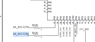
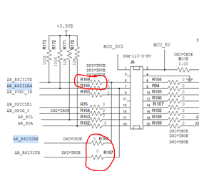
My question is, how can I reroute the UART from the USB port to somewhere else like the BP/LP header? I can see in the schematics that there are many connections to AR_RS232TX/RX on the board, but none of those points show any data when probed. 

Any help is much appreciated.

Thanks,
Nicolaj

  • Hello

    Have you looked at the EVM UG  to understand how the Muxes available on the board  decide the routing of these signals.

    Thank you,

    Vaibhav

  • Hello Vaibhav,

    Thanks for the reply. I have read the user's guide for the EVM (this one https://www.ti.com/lit/pdf/swru518)  but I found no useful information pertaining to my original question. Could you please point me in the direction of something I may have missed?

    Since posting the original question I have tried simply changing the UART TX pin to be the same as the DS3 user LED:

    modified:
        
        Pinmux_Set_OverrideCtrl(SOC_XWR14XX_PINN13_PADAZ, PINMUX_OUTEN_RETAIN_HW_CTRL, PINMUX_INPEN_RETAIN_HW_CTRL);
        Pinmux_Set_FuncSel(SOC_XWR14XX_PINN13_PADAZ, SOC_XWR14XX_PINN13_PADAZ_MSS_UARTB_TX); 
        ...
        gMmwMCB.commandUartHandle = UART_open(1, &uartParams);
    
    instead of originally:
    
        Pinmux_Set_OverrideCtrl(SOC_XWR14XX_PINN6_PADBE, PINMUX_OUTEN_RETAIN_HW_CTRL, PINMUX_INPEN_RETAIN_HW_CTRL);
        Pinmux_Set_FuncSel(SOC_XWR14XX_PINN6_PADBE, SOC_XWR14XX_PINN6_PADBE_MSS_UARTA_TX);
        ...
        gMmwMCB.commandUartHandle = UART_open(0, &uartParams);

    I also removed the PINN13 conversion to GPIO_2 in the code to avoid any conflict.
    However, I am not seeing the expected result (UART signal on DS3 LED), I only observe that the UART signal from the USB port disappears. I am not quite sure what the different UART enumerations (UART-1/3, UARTA/B) mean and if they affect which pins can be used and if this is somehow related to SCI-A/B when choosing the UART_config.

    Thanks,
    Nicolaj

  • Hello Nicolaj,

    Please refer to the schematics to get the UART/RS232 routing options. You need to disconnect the resisters R128 and R129 going to the TM4C chipset (for USB connection) and mount the resisters depending on the path you need. For example mount R169 and R166

    Regards,

    Vivek

  • Hello Vivek,

    Thanks for your reply.
    So copying or re-routing the UART signal to another pin purely programmatically is not possible?

    Thanks,
    Nicolaj

  • Hello Nicolaj,

    That is correct. 

    Regards,

    Vivek