This thread has been locked.

If you have a related question, please click the "Ask a related question" button in the top right corner. The newly created question will be automatically linked to this question.

TDC1000: Transducer change and related issues for TDC1000-7200EVM module

Part Number: TDC1000
Other Parts Discussed in Thread: MSP430F5528, TUSS4470

Good morning, there. 

I am Minrak working in KIST and I encountered problem using ultrasonic transducer.

I want to decrease the water tank size so I tried decreasing transducer size from 10 mm to 7 mm.
Before changing tank size, I tried using the transducer size with 7 mm (DISC) instead of 10 mm (DISC) and filled water to 1 cm from the bottom of tank (tank thickness is 3 mm, tank geometry is shell with inner diameter of 12 mm, so higher than 10 mm).

All set-up was the same for 10 mm and 7 mm as well. But the water level is not correct for 7 mm and I know it as there is no TOF change when I increased water level from 1 cm to 2 cm.
For 10 mm, it works well. 

So I am asking for help how to make it correct. What GUI setting or physical configuration change for 7 mm?
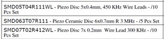
Please check the specs from the website links of STEMINC.

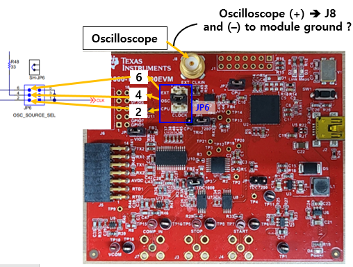
Here, I attach the specs of each (10 mm, 7 mm transducers) and GUI settings. The GUI setting was the same as in the last picture.
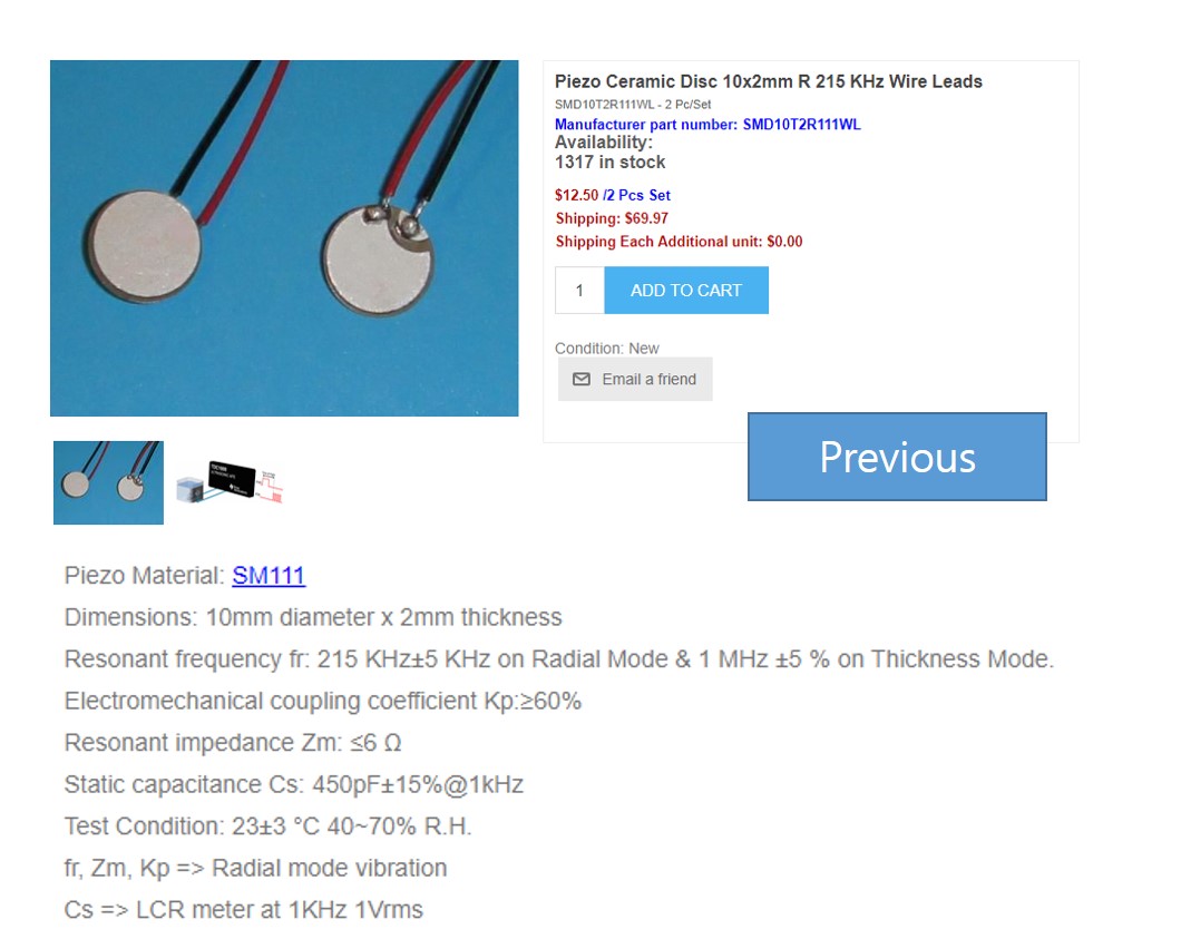
Previous (10 mm):

(Website link: https://www.steminc.com/PZT/en/piezo-ceramic-disc-10x2mm-r-215-khz-wire-leads-smd10t2r111wl)

Current:

(Website link: https://www.steminc.com/PZT/en/disc-7x05mm-r-wire-leads-4-mhz)
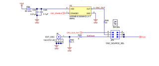
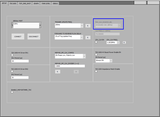
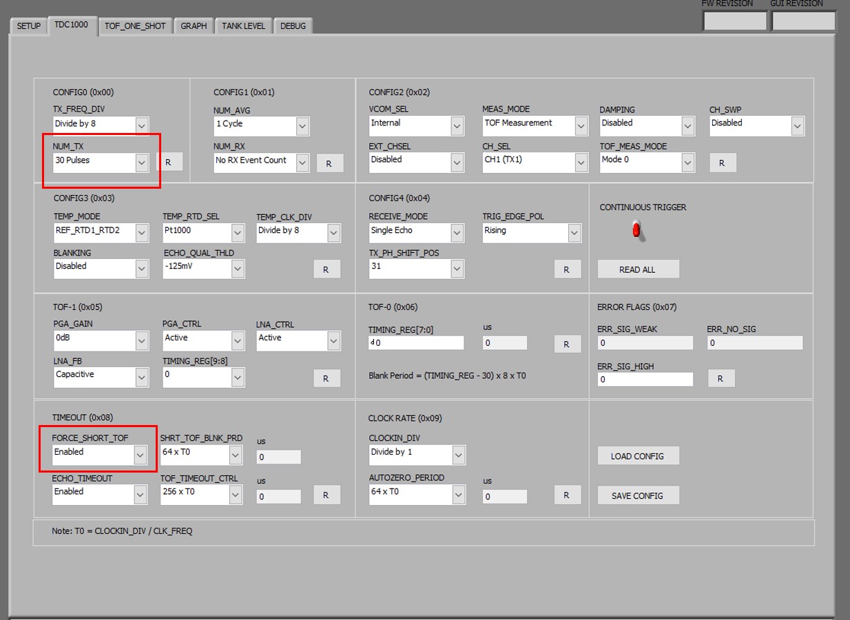
GUI setting
:

The most difference seems to be frequency and capacitance. But as you have more expertise in this field, could you please give me advice?

Best regards,
Minrak 

  • Hello Minrak,

    Thank you for the question and all the detailed information.

    Upon reviewing the information submitted for both the Steminc SMD10T2R111WL 10mm transducer and the Steminc SMD07T05R412WL 7mm transducer: the reason why you are not getting a correct result is because the transducers resonant frequency of the 7mm transducer is 4.25MHz when your previous transducer had a resonant frequency of 1MHz.

    There are two things to pay notice on why the transducer is not working, the first one being that the TDC1000 spec limit for operating frequency is 4MHz, so the 7mm will not work with this device since it is out of the operating range with a 4.25MHz signal needed to drive this transducer.

    The second reason is the setup it does not apply for this situation since the frequency is out of range. But in case you are interested in using another frequency transducer with the device you must update the TX_FREQ_DIV setting, this takes the internal 8MHz clock on the TDC1000-TDC7200EVM and divides by 8 (your current setting) in order to producer the 1MHz signal needed to drive your 10mm transducer. In other words you have to ensure that your internal clock is being divided to match the transducers resonant frequency. If you cannot divide 8MHz to get your desired frequency, you may always use an external clock and divide that accordingly. The clock frequency can be anywhere between 1-16MHz if using the GUI.

    I hope this helps!

    Best,

    Isaac

  • Thank you for your replies,

    So i need to use transducer with frequency lower than 4 MHz.

    Therefore, I consider the below as substitutes. 

    1. But as the module has internal clock of  8 MHz, it seems like the above transducer frequencies cannot be matched by any TX_FREQ_DIV.
    For example, SMD05T04R111WL from the above table has frequency of 0.45 MHz, so if I divide by 16, the module frequency can be
    8 MHz / 16 -> 0.5 MHz but it is still different from 0.45 MHz.

    Could you please tell me what I can do to match the transducers represented above? 

    2. And could you tell me the meaning of TX_FREQ_DIV? Is it like decreasing module frequency to match the transducer?

    3. Finally, 10 mm in the previous question has the frequency of 0.215 MHz, not 1 MHz.
    Not wired type (SMD10T2R111) has 1 MHz but I am using wired type. You can check again as in the image. 
    Do you think it is typo of STEMINC so you think 1 MHz is right?

    I will look forward to your replies and thank you for your past answer. 


    Best regards,
    Minrak Kim

  • Hello Minrak,

    The transducer you choose mainly depends on the application so please keep that in mind when choosing a transducer. For applications coupled with liquids we typically recommend using 1MHz and above, if the applications involves sensing through air then 40kHz to a couple of hundred kHz will work mostly dependent on the distance you are trying to measure.

    With the TDC1000 I typically recommend using a transducer 1MHz and above. To answer your questions:

    1) Since the TX_FREQ_DIV only works in powers of 2, the option of using an external clock source is given on the EVM. You can move the shunt on JP6 and provide the external clock via J8.Using the divide by 16 option would not work because the difference would be too large in the transducers resonant frequency so you need to use a clock frequency that can be divided appropriately by TX_FREQ_DIV.


    So if trying to match the 450kHz transducer you may use an external 1.8MHz clock and set TX_FREQ_DIV to divide the clock by 4.

    2) Yes, the TX_FREQ_DIV is used to decrease the input clock frequency to match the transducers operating frequency.

    3) My mistake on this one the transducer mentioned is a 215kHz transducer and not a typo on Stemincs behalf.

    I hope this helps and let me know if you have any further questions!

    Best,

    Isaac

  • Thank you for your replies.

    1. Regarding your answer 1), I want to check whether what I understand is correct.
    It seems that J8 is connected to 2nd pin of JP6 inside the module circuit. 
    Therefore, I just need to buy and connect "clamp type plug" (for example, https://kr.mouser.com/datasheet/2/643/pi-CCS-JOHN-142-0207-016-1290205.pdf) to connect with the external oscilloscope? Or can I also connect (+) of the oscilloscope to J8 and connect (-) of the oscilloscope with (-) of module together? Could you please tell me what connector I need to buy? (Link for the specific product or terminology will be appreciated).

    2. Could you tell me the waveform (sine, square) and the amplitude (max - min) of the oscilloscope? 

    3. With the external clock, how can I change the blue-marked in the below GUI?


    4. So far, I have used  215kHz transducer (10 mm) with the default TX_FREQ_DIV (Divide by 8) but still could measure 
    the height of the liquid. Would it be more accurate if I set the external clock and try again?

    Best regards,
    Minrak Kim

  • Hello Minrak,

    1) Yes, J8 is connected directly to pin 2 of the JP6 jumper. But just to be clear J8 is not used to connect to an oscilloscope. It is used to connect to an external clock source or a function generator in order to generate the clock needed by the devices. You may be able to use the CPU clock as well for this, moving the shunt on JP6 to position 5 and 6 and updating the GUI to use the CPU clock at 1.7143MHz (1.7143MHz/8 = 214.29kHz) this should be close enough to get the proper performance.

    If you would like to use the external clock though you would need an SMA Female connector if it is not populated for J8 and then depending on your external clock you will mostly likely need an SMA to BNC connector, but keep in mind this depends on your equipment, I am not familiar with what connectors will be on the devices you are using.

    2) The clock signal used is typically ~3.3V square wave, if you need more info on the clock signal you can take a look at the datasheet here or probe the internal clock (pin 4 of JP6) this should give you the info you are looking for.

    3) In order to make the changes you need to have the EVM connected. If the EVM is not connected it will look greyed out like it does in your image. With a device connected, to use external clock or CPU clock, click on the TDC_CLK_SOURCE_SEL dropdown and select EXT_CLK or CPU (make sure to also change the shunt on JP6 to the position you selected on the GUI). 

    For External Clock- Type the frequency you are using on CLK FREQ box source must be from 1MHz-16MHz.

    For CPU Clock- Check the CPU_CLK EN box and choose the frequency would like to use in the CPU_CLK FREQ dropdown.

    4) Technically using the 1MHz signal should not work but perhaps because 215kHz is a close enough multiple to the 1MHz signal could be part of the reason why it is operating. I have not tested this instance so I do not have much to comment on the accuracy of this measurement but the proper use of the device would be to transmit using the proper frequency and perform the measurements that way.

    Best,

    Isaac

  • Thank you very much, Isaac

    1. Regarding your answer 1), does CPU clock is that the clock source is generated by computer?
    And for your recommendation, it works a lot better when I used CPU 1.7143MHz (1.7143MHz/8 = 214.29kHz) for 215 kHz transducer!
    Thank you very much for your advices.


    2. And one additional question: Transducers don't vibrate visibly for any frequencies.
    For other commercial ultrasonic level sensors (https://www.ysi.com/wl705), they apparently vibrate and it can be seen with the bare eyes. 
    Is it because the transducers for TDC modules have lower amplitude then others? Or is it because the principle of measuring level is different?

    The performance is a lot better than the commercial sensors like above but I ask you as I want to know the reason. 

    3. Finally, I am considering change in Num_Tx and Force_short_TOF as in the below.


    Can change in Num_TX and Force_short_TOF bring about different TOF value?
    If so, is there any suggestion for my setup or different recommended Num_TX / Force_short_TOF for certain level of water?

    Best regards,
    Minrak Kim

  • Hello Minrak,

    1) No the CPU clock is not generated by the computer, it is generated by the MSP430F5528 on board to generate the clock signal. Glad that you got a better performance out of it!

    2) I do not have much information on this since I have never seen an ultrasonic transducer move before, but I would imagine if that's the case then its probably transmitting a large amount of SPL (sound pressure level) through the medium. So perhaps a slower frequency 40kHz or so and the transmission voltage might play a part in this. The principle of measurement should be the same but the specifications of the measurement might be the ones making a difference.

    For the link to the device you provided I could not find operating frequency for it and it has a max voltage of 30V which can help you achieve longer distances but for degrades the performance at closer ranges. The TDC1000 on the EVM drives transducers at about ~5.5V peak to peak so it does not have the best range but you could always outfit the output with a transformer if you are trying to obtain levels that high. Although for something with a longer range I would recommend our TUSS4470 device.

    3) Changing NUM_TX will increase the amount of pulses you are transmitting to 30, but the more pulses you transmit you sacrifice the minimum measurement you can obtain, so you have to find a good balance between SNR and minimum distance needed. FORCE_SHORT_TOF is a different mode used to obtain short ToF measurements, what this does is give you the ability to trigger your echo listening window earlier than you get in the standard ToF measurement mode. Use of this mode mainly depends on what are your expected water levels so it is difficult to make suggestions without more application specifications.

    This FAQ should help you with many questions about the setup: e2e.ti.com/.../faq-tdc1000-everything-you-need-to-know-for-ultrasonic-tof-liquid-coupled-collateral-tools-designs-faq

    Best,

    Isaac