This thread has been locked.

If you have a related question, please click the "Ask a related question" button in the top right corner. The newly created question will be automatically linked to this question.

IWR1843BOOST: IWR1843BOOST

Part Number: IWR1843BOOST
Other Parts Discussed in Thread: UNIFLASH, , AWR1642, AWR1843

Hi,  I must be close now - I'm nearly all there in mmWave Studio: the device connects, seems to configure and I can run a frame, which seems to take the right sort of time, based on the DCA1000 training video.  However, I'm not getting any data - no *.bin file, and the logs it does produce indeed say no bytes transferred.  Hopefully this is just something I've got wrong in the DATA CONFIG tab?  I'm just using the default values it gives, and I have set things like 77GHZ, xWR1843 etc. The

09-Aug-2021 09:37:20: IsFPGA:,0,0,
09-Aug-2021 09:37:21: C:\ti\mmwave_studio_02_01_01_00\mmWaveStudio\RunTime,0,
09-Aug-2021 09:37:23: API:select_capture_device,DCA1000,0,
09-Aug-2021 09:37:37: API:select_chip_version,AR1642,0,
09-Aug-2021 09:38:04: API:select_chip_version,AR1642,0,
09-Aug-2021 09:38:22: API:ChannelConfig,3,15,0,
09-Aug-2021 09:38:22: API:AdcOutConfig,2,1,0,
09-Aug-2021 09:38:22: API:DataFmtConfig,15,2,1,0,1,0,
09-Aug-2021 09:38:39: API:LowPowerConfig,0,0,0,
09-Aug-2021 09:40:49: API:update_num_adc_files_and_frames,1,8,1,0,
adc_data_config_1_Raw_LogFile.csvvideo doesn't mention x18 parts, so hopefully its going to be a simple config change to fix this.  Thanks.

  • Hi Alan

    Are you able to complete all the initialization steps from Reset to RF Power Up?

    Regards,

    AG

  • Hi Akash,

    well in so far as it lets me press the buttons on the GUI, yes - but I have no independent test equipment to confirm whether any RF is actually being generated.  Also as far as I know, I have the ethernet set up as per the video, as this might also cause lack of data, but perhaps that would be lots of data... just all zeros?  All the connections are green and I've done the firmware downloads etc.  Is there anything else I can look at to be sure its all configured OK?  It is producing some heat by this stage - its got that faint "new electronics" smell that it didn't before I got this far, so something seems to be happening.  And, running the frame leads me to think that its doing something - the button on the GUI changes for about the right sort of time, and it is producing logs - but no .bins.

    Just in case its part of it - the post process button doesn't seem to do anything.  Should it actually open the matlab script, as shown on the video?

    Many thanks, Alan

  • Hi Alan,

    Looking at your log file, it shows that no data was recorded and the duration of the recording time was 0

    From my experience, this is usually caused by issues with the hardware setup which prevent the data from being correctly uploaded to the host machine. Be sure to check the SOP headers and switches are set correctly.  To my understanding, the configurations you have set in the GUI are fine since the connections are all green and you were able to generate a log file. 

    These attached slides may be useful for verifying that the hardware was set up correctly. They also provide a good overview of the rest of the steps as well which would be worth double checking as well. These are targeted for the XWR6843, however, most of this will still apply for the xWR1843

    5040.mmWave_sensor_raw_data_capture_using_DCA1000_68xx.pptx

    As for the post processing, that will only work once there is a .bin file to process. Once the post-process button is pressed, it will automatically launch the script and create the plot GUI

    Best regards,

    Drew D

  • Hi Drew,

    thanks - I'll go through all that tomorrow.  My DCA1000 is just set exactly as it arrived - haven't yet got as deep in as all its switches, and the IWR SOP switches are set as I believe the DCA  video says (this seems to be different for the Visualizer s/w) as 011 which should be debug mode.

    best regards

    Alan

  • Hi Drew,

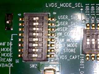
    looking at the DCA switches, SW2.5 is set to "CONFIG_VIA_SW" , so presumably the rest of the switches have no effect, and everything is controlled by mmWave Studio?  Do you think this is purely a DCA issue i.e. the IWR is probably working now?  What else could I check to determine what is/isn't working - not lease so I can give you good info to be able to diagnose things.

    thanks

    Alan

  • Hi Alan,

    Have you checked the output terminal for error messages when recording data? This can be done in two ways:

    • View -> Output, then the output terminal should open
    • open CLI_log.txt, which is generated in the same path where you found the adc log file you sent in the first post

    Check for error messages in these as you run through the set-up process. Since no .bin file is generated, the error you should be looking for will be: "No LVDS Data". This will occur between the "Start Record" and "Stop Record Commands"

    One thing I noticed in your log files, it seems like the SW is detecting a 1642 device, but you mentioned you were using the xWR1843. Are you selecting this option under the "connection" panel?

  • Hi Drew,

    I've got the OUTPUT screen up - attached in the .txt: looks like the 1843 is being selected (I think I had before, but can't show evidence for this).  Also attached the setup scree in .docx, so you can see that I should have x18xx firmwares selected too.  However, the OUTPUT screen definitely shows errors, with the firmware not matching.  Can you see from this what I've done wrong?

    thanks

    Alan

    configScreen.docx

    	  [17:05:27]  [RadarAPI]: ar1.Calling_IsConnected()
    	  [17:05:27]  [RadarAPI]: ar1.SaveSettings('C:\Users\Alan_3_Normal\AppData\Roaming\RSTD\ar1gui.ini')
    	  [17:06:15]  [RadarAPI]: ar1.Connect(27,921600,1000)
    	  [17:06:18]  [RadarAPI]: Warning: Connected with baudrate 115200
    	  [17:06:19]  [RadarAPI]: Warning: Disconnected existing BaudRate
    	  [17:06:19]  [RadarAPI]: Warning: Trying to connect with baudrate 921600
    	  [17:06:20]  [RadarAPI]: ar1.Calling_IsConnected()
    	  [17:06:22]  [RadarAPI]: ar1.SelectChipVersion("AR1642")
    	  [17:06:22]  [RadarAPI]: Status: Passed
    	  [17:06:22]  [RadarAPI]: ar1.SelectChipVersion("XWR1843")
    	  [17:06:22]  [RadarAPI]: Status: Passed
    	  [17:06:22]  Device Status : XWR1843/QM/SOP:2/ES:2
    	  [17:06:22]  [RadarAPI]: ar1.SaveSettings('C:\Users\Alan_3_Normal\AppData\Roaming\RSTD\ar1gui.ini')
    	  [17:06:23]  [RadarAPI]: ar1.DownloadBSSFw("C:\\ti\\mmwave_studio_02_01_01_00\\rf_eval_firmware\\radarss\\xwr18xx_radarss.bin")
    	  [17:06:24]  [RadarAPI]: Downloading BSS Patch RPRC Binary..
    	  [17:06:25]  [RadarAPI]: ar1.GetBSSFwVersion()
    	  [17:06:25]  [RadarAPI]: BSSFwVersion:(02.00.00.01 (05/10/17))
    	  [17:06:26]  [RadarAPI]: ar1.DownloadMSSFw("C:\\ti\\mmwave_studio_02_01_01_00\\rf_eval_firmware\\masterss\\xwr18xx_masterss.bin")
    	  [17:06:26]  [RadarAPI]: Downloading MSS RPRC Binary..
    	  [17:06:26]  [RadarAPI]: ar1.GetBSSPatchFwVersion()
    	  [17:06:26]  [RadarAPI]: BSSPatchFwVersion:(01.02.05.02 (00/00/00))
    	  [17:06:28]  [RadarAPI]: ar1.GetMSSFwVersion()
    	  [17:06:28]  [RadarAPI]: MSSFwVersion:(01.02.05.02 (16/07/19))
    	  [17:06:30]  [RadarAPI]: ar1.PowerOn(0, 1000, 0, 0)
    	  [17:06:30]  [RadarAPI]: Status: Passed
    	  [17:06:30]  MSS power up done async event received!
    	  [17:06:32]  [RadarAPI]: ar1.SelectChipVersion("AR1642")
    	  [17:06:32]  [RadarAPI]: Status: Passed
    	  [17:06:32]  [RadarAPI]: ar1.SelectChipVersion("XWR1843")
    	  [17:06:32]  [RadarAPI]: Status: Passed
    	  [17:06:32]  Device Status : XWR1843/QM/SOP:2/ES:2
    	  [17:06:32]  [RadarAPI]: ar1.RfEnable()
    	  [17:06:32]  [RadarAPI]: Status: Passed
    	  [17:06:32]  BSS power up done async event received!
    	  [17:06:33]  [RadarAPI]: ar1.GetMSSFwVersion()
    	  [17:06:33]  [RadarAPI]: MSSFwVersion:(01.02.05.02 (16/07/19))
    	  [17:06:33]  [RadarAPI]: ar1.GetBSSFwVersion()
    	  [17:06:33]  [RadarAPI]: BSSFwVersion:(02.00.00.01 (05/10/17))
    	  [17:06:34]  [RadarAPI]: ar1.GetBSSPatchFwVersion()
    	  [17:06:34]  [RadarAPI]: BSSPatchFwVersion:(01.02.05.02 (30/04/19))
    	  [17:06:34]  [RadarAPI]: Warning: BSS patch firmware version Mismatch!
    	  [17:06:41]  [RadarAPI]: ar1.ChanNAdcConfig(1, 1, 0, 1, 1, 1, 1, 2, 1, 0)
    	  [17:06:41]  [RadarAPI]: Status: Passed
    	  [17:06:43]  [RadarAPI]: ar1.RfLdoBypassConfig(0x1)
    	  [17:06:43]  [RadarAPI]: Status: Passed
    	  [17:06:45]  [RadarAPI]: ar1.LPModConfig(0, 0)
    	  [17:06:45]  [RadarAPI]: Status: Passed
    	  [17:06:46]  [RadarAPI]: ar1.RfInit()
    	  [17:06:47]  [RadarAPI]: Status: Failed, Error Type: RESP TIMEOUT
    	  [17:06:55]  [RadarAPI]: ar1.DataPathConfig(513, 1216644097, 0)
    	  [17:06:59]  Status: Failed, Error Type: RESP TIMEOUT
    	  [17:07:01]  [RadarAPI]: ar1.LvdsClkConfig(1, 1)
    	  [17:07:05]  Status: Failed, Error Type: RESP TIMEOUT
    	  [17:07:14]  [RadarAPI]: ar1.ProfileConfig(0, 77, 100, 6, 60, 0, 0, 0, 0, 0, 0, 29.982, 0, 256, 10000, 0, 0, 30)
    	  [17:07:18]  Status: Failed, Error Type: RESP TIMEOUT
    	  [17:07:18]  [RadarAPI]: ar1.ChirpConfig(0, 0, 0, 0, 0, 0, 0, 1, 0, 0)
    	  [17:07:22]  Status: Failed, Error Type: RESP TIMEOUT
    

  • Hi Alan,

    It looks like you are getting timeout errors over the COM port when sending configurations to the xWR1843.

    In the screenshot you sent me, you are connecting to com port 27 with baud rate 921600. The port used to send configurations to the xWR1843 typically uses a baud rate of 115200 and should be connected to the port labeled "XDS110 Class Application/User UART" Check your device manager to make sure that you are setting the correct port number.

    The "XDS100 Class Auxiliary Data Port" is used for the streaming of data over UART and connects with the baud rate of 921600. I think that this is what you might be connecting to, however, since we are capturing data straight from the ADC we won't need to connect to this port. 

  • Hi Drew,

    right com port, just wrong speed - I went with the default it suggested.  Changed now to slower, and everything seems to go well until I get to to RF INIT, and I can't get passed:

    [09:31:32] [RadarAPI]: ar1.RfInit()
    [09:31:33] [RadarAPI]: Status: Failed, Error Type: RESP TIMEOUT

    All seems OK up till this point - perhaps we're getting close to where the problem is.  For info, I find that mmWave Studio is not very good at seeing all the com ports: check via windows that everything is attached & OK, do a REFRESH, but often I only get my own 2 ports, the 4 on the DCA, but getting the XDS's up can take several attempts, including exiting/switch off and try again.  Can't say if this is an issue with my PC setup.

    What do I need to look at next to get RF INIT - and hopefully the rest - going?

    many thanks

    Alan

  • Hi Alan, 

    Could you send me the full execution log leading up to the timeout error? Also, a screen shot of the settings you input in the Static Configuration tab would be helpful too. 

    For the issue with the ports, did you have trouble detecting them on your PC when running the Out-of-Box demo with the stand alone xWR1843? Or has this issue only come up when connected to the DCA1000 and running through mmWaveStudio?

  • Hi Drew,

    I was just about to add some info!  I'm sure you said, but can you remind me where the log file is stored & what its called?  In the meantime I've screenShotted the GUI at connection, what deviceManager says at the same time and the contents of the OUTPUT window.

    I haven't managed to get the IWR out of the box (Visualiser?) working - it always fails at "down load XDS emulator" which I've done. and deviceManager seems OK, so I'd guess the "drivers level" is OK and J8 USB is connected and recognised.

    There's something going on around the XDS ports: deviceManager see them; mmWave can (after a few refreshes & power off/on the modules) see them and allows me to continue on com27.  However, once at RFINIT, going back shows all commands time out, and if I go back and start the connection again, the refresh doesn't see com27/28 anymore - looks like its lost the port par way through?

    Just to add what I came on-line to say: I have a (very) old GUI I wrote which does the same sort of thing: it loops round comX asking if its there or not.  It never finds com27 or 28, but stops at 24, which is the DCA ones, and matches what mmWave reliably finds.  Bear in mid though, this is very much "engineer's bench software"!

    Could mmWave (and perhaps Visualiser) be having problems with the com port numbers?  As I hadn't found the OUTPUT tab earlier, I can't be sure of just when problems actually occurred in our earlier conversation i.e. this may been happening all along, I just thought I'd got further etc.

    connectScreenShot.docx

    							      GM: Constructor
    							      GM: Wed Aug 11 15:04:21 2021
    							      RSTD.Transmit("/Settings")
    							      [15:04:21]  
    							      [15:04:21]  ### Running Startup script: "C:\ti\mmwave_studio_02_01_01_00\mmWaveStudio\Scripts\Startup.lua" ###
    							      [15:04:21]  RSTD.SetAndTransmit ("/Settings/Scripter/Display DateTime" , "1")
    							      [15:04:21]  RSTD.SetAndTransmit ("/Settings/Scripter/DateTime Format" , "HH:mm:ss")
    							      [15:04:21]  Scripter ignored: Attempt to UnBuild() again or before Build.
    							      [15:04:21]  RSTD.SetVar ("/Settings/Clients/Client 0/Dll" , "C:\\ti\\mmwave_studio_02_01_01_00\\mmWaveStudio\\Clients\\\\LabClient.dll")
    							      [15:04:21]  RSTD.SetVar ("/Settings/Clients/Client 0/Use" , "TRUE")
    							      [15:04:21]  RSTD.SetVar ("/Settings/Clients/Client 1/Use" , "FALSE")
    							      [15:04:21]  RSTD.SetVar ("/Settings/Clients/Client 2/Use" , "FALSE")
    							      [15:04:21]  RSTD.SetVar ("/Settings/Clients/Client 3/Use" , "FALSE")
    							      [15:04:21]  RSTD.SetVar ("/Settings/Clients/Client 4/Use" , "FALSE")
    							      [15:04:21]  RSTD.SetVar ("/Settings/AL Client/AL Dll" , "C:\\ti\\mmwave_studio_02_01_01_00\\mmWaveStudio\\RunTime\\SAL.dll")
    							      [15:04:21]  RSTD.SetVar ("/Settings/Clients/Client 0/GuiDll" , "")
    							      [15:04:21]  RSTD.SetVar ("/Settings/AutoUpdate/Enabled" , "TRUE")
    							      [15:04:21]  RSTD.SetVar ("/Settings/AutoUpdate/Interval" , "1")
    							      [15:04:21]  RSTD.SetVar ("/Settings/Monitors/UpdateDisplay" , "TRUE")
    							      [15:04:21]  RSTD.SetVar ("/Settings/Monitors/OneClickStart" , "TRUE")
    							      [15:04:21]  RSTD.SetVar ("/Settings/Automation/Automation Mode" , "false")
    							      [15:04:21]  RSTD.Transmit("/")
    							      [15:04:21]  RSTD.SaveSettings(): Settings saved to "C:\Users\Alan_3_Normal\AppData\Roaming\RSTD\config.xml"
    							      [15:04:21]  RSTD.Build()
    							      [15:04:21]  RSTD.SaveSettings(): Settings saved to "C:\Users\Alan_3_Normal\AppData\Roaming\RSTD\config.xml"
    							      [15:04:21]  RSTD.Transmit("/")
    							      [15:04:21]  RSTD.AL_Build()
    							      [15:04:21]  RSTD.AL_LoadXml()
    							      [15:04:21]  RSTD.Transmit("/")
    							      [15:04:21]  RSTD.AL_Init()
    							      [15:04:21]  RSTD.Clients_Build()
    							      [15:04:21]  GM: Init
    							      [15:04:21]  GM: Loaded 'C:\ti\mmwave_studio_02_01_01_00\mmWaveStudio\Clients\\LabClient.dll'
    							      [15:04:21]  GM: 1 Guest (s) init
    							      [15:04:21]  GM: 1 Module(s) init
    							      [15:04:21]  GM: 2 Tab   (s) init
    							      [15:04:21]  RSTD.Client_LoadXml()
    							      [15:04:22]  [RadarAPI]: ar1.selectRadarMode(0)
    							      [15:04:22]  [RadarAPI]: Status: Passed
    							      [15:04:22]  Matlab Runtime Engine is installed
    							      [15:04:22]  [RadarAPI]: Starting Matlab Engine..
    							      [15:04:25]  [RadarAPI]: Matlab Engine Started!
    							      [15:04:27]  [RadarAPI]: ar1.selectCascadeMode(0)
    							      [15:04:27]  [RadarAPI]: Status: Passed
    							      [15:04:27]  [RadarAPI]: ar1.LoadSettings('C:\Users\Alan_3_Normal\AppData\Roaming\RSTD\ar1gui.ini')
    							      [15:04:27]  TESTING = false
    							      [15:04:27]  RstdNet: Port 2777: Listening..
    							      [15:04:27]  
    							      [15:04:27]  ***Script completed successfully.***
    							      [15:04:29]  [RadarAPI]: Opening Gpio Control Port()
    							      [15:04:29]  [RadarAPI]: Status: Passed
    							      [15:04:30]  [RadarAPI]: Opening Board Control Port()
    							      [15:04:30]  [RadarAPI]: Status: Passed
    							      [15:04:31]  [RadarAPI]: ar1.FullReset()
    							      [15:04:31]  [RadarAPI]: Status: Passed
    							      [15:04:32]  [RadarAPI]: Closing Board Control Port()
    							      [15:04:32]  [RadarAPI]: Status: Passed
    							      [15:04:32]  [RadarAPI]: Closing Gpio Control Port()
    							      [15:04:32]  [RadarAPI]: Status: Passed
    							      [15:04:32]  [RadarAPI]: ar1.SOPControl(2)
    							      [15:04:32]  [RadarAPI]: Status: Passed
    							      [15:05:10]  [RadarAPI]: ar1.Connect(27,115200,1000)
    							      [15:05:11]  [RadarAPI]: ar1.Calling_IsConnected()
    							      [15:05:12]  [RadarAPI]: ar1.SelectChipVersion("AR1642")
    							      [15:05:12]  [RadarAPI]: Status: Passed
    							      [15:05:12]  [RadarAPI]: ar1.SelectChipVersion("AR1642")
    							      [15:05:12]  [RadarAPI]: Status: Passed
    							      [15:05:12]  [RadarAPI]: ar1.deviceVariantSelection("XWR1843")
    							      [15:05:12]  [RadarAPI]: Status: Passed
    							      [15:05:12]  [RadarAPI]: ar1.frequencyBandSelection("77G")
    							      [15:05:12]  [RadarAPI]: ar1.SelectChipVersion("XWR1843")
    							      [15:05:12]  [RadarAPI]: Status: Passed
    							      [15:05:12]  Device Status : XWR1843/QM/SOP:2/ES:2
    							      [15:05:12]  [RadarAPI]: ar1.SaveSettings('C:\Users\Alan_3_Normal\AppData\Roaming\RSTD\ar1gui.ini')
    							      [15:05:20]  [RadarAPI]: ar1.DownloadBSSFw("C:\\ti\\mmwave_studio_02_01_01_00\\rf_eval_firmware\\radarss\\xwr18xx_radarss.bin")
    							      [15:05:20]  [RadarAPI]: Downloading BSS Patch RPRC Binary..
    							      [15:05:28]  [RadarAPI]: ar1.GetBSSFwVersion()
    							      [15:05:28]  [RadarAPI]: BSSFwVersion:(02.00.00.01 (05/10/17))
    							      [15:05:29]  [RadarAPI]: ar1.GetBSSPatchFwVersion()
    							      [15:05:29]  [RadarAPI]: BSSPatchFwVersion:(01.02.05.02 (30/04/19))
    							      [15:05:30]  [RadarAPI]: ar1.DownloadMSSFw("C:\\ti\\mmwave_studio_02_01_01_00\\rf_eval_firmware\\masterss\\xwr18xx_masterss.bin")
    							      [15:05:30]  [RadarAPI]: Downloading MSS RPRC Binary..
    							      [15:05:41]  [RadarAPI]: ar1.GetMSSFwVersion()
    							      [15:05:41]  [RadarAPI]: MSSFwVersion:(01.02.05.02 (16/07/19))
    							      [15:05:43]  [RadarAPI]: ar1.PowerOn(0, 1000, 0, 0)
    							      [15:05:43]  [RadarAPI]: Status: Passed
    							      [15:05:43]  MSS power up done async event received!
    							      [15:05:45]  [RadarAPI]: ar1.SelectChipVersion("AR1642")
    							      [15:05:45]  [RadarAPI]: Status: Passed
    							      [15:05:45]  [RadarAPI]: ar1.SelectChipVersion("XWR1843")
    							      [15:05:45]  [RadarAPI]: Status: Passed
    							      [15:05:46]  Device Status : XWR1843/QM/SOP:2/ES:2
    							      [15:05:46]  [RadarAPI]: ar1.RfEnable()
    							      [15:05:46]  [RadarAPI]: Status: Passed
    							      [15:05:46]  BSS power up done async event received!
    							      [15:05:46]  [RadarAPI]: ar1.GetMSSFwVersion()
    							      [15:05:46]  [RadarAPI]: MSSFwVersion:(01.02.05.02 (16/07/19))
    							      [15:05:47]  [RadarAPI]: ar1.GetBSSFwVersion()
    							      [15:05:47]  [RadarAPI]: BSSFwVersion:(02.00.00.01 (05/10/17))
    							      [15:05:47]  [RadarAPI]: ar1.GetBSSPatchFwVersion()
    							      [15:05:47]  [RadarAPI]: BSSPatchFwVersion:(01.02.05.02 (30/04/19))
    							      [15:05:58]  [RadarAPI]: ar1.ChanNAdcConfig(1, 1, 0, 1, 1, 1, 1, 2, 1, 0)
    							      [15:05:58]  [RadarAPI]: Status: Passed
    							      [15:06:08]  [RadarAPI]: ar1.RfLdoBypassConfig(0x1)
    							      [15:06:08]  [RadarAPI]: Status: Passed
    							      [15:06:11]  [RadarAPI]: ar1.SetMiscConfig(0)
    							      [15:06:11]  [RadarAPI]: Status: Passed
    							      [15:06:13]  [RadarAPI]: ar1.RfInit()
    							      [15:06:14]  [RadarAPI]: Status: Failed, Error Type: RESP TIMEOUT
    							      [15:06:19]  [RadarAPI]: ar1.RfLdoBypassConfig(0x1)
    							      [15:06:23]  Status: Failed, Error Type: RESP TIMEOUT
    

  • Hi Alan, 

    That is useful info to know, thank you. I think this issue with the XDS ports might be the cause of your connection problems. To better isolate this issue, could you try running through the OOB (Out-of-box) demo for your xWR1843 again,

    here are the instructions: https://dev.ti.com/tirex/explore/node?node=AH1yn4Yr-VrqkN65pfhtXg__VLyFKFf__LATEST

    When you get the "download XDS emulator" error, could you take some screenshots and document any logs or error messages? Additionally, could you also post a picture of your hardware set up when running OOB demo

  • Hi Drew,

    OK - the instructions need quite a bit more downloading & installing, so may take a little while - I'll let you know once its done.

    thanks
    Alan

  • Hi Drew,

    well, lots of down-loading & isntallations later.... I've done a bit of detective work, and rather than do lots of typing in here, I've put it in a text file for easier use.  Text plus two screen shots attached.

    thanks

    Alan

    visualserOffLineUsbConnect.docx

    I think I've downloaded and installed installed everything specified (installs can be very slow).  I'm also a little 
    concerned installing lots of stuff, as the last lot (SDK, mmWave and the off-line visualiser) trashed my c: 
    drive - it came up with "no bootable media"!  This is actually relevant still, as I'll tell you.
    
    Let's go for the FLASH first: screen-shot attached, this seems to run OK, but can't connect to the USB 
    ports - although it seems to see them OK.
    
    In the on-line visualiser, where it sticks at "download XDS etc", there is also a "yes I've done this" choice, 
    which says something about the XDS stuff being user specific, and words about administrator & ordinary users.
    This is exactly what I do on PCs, I never operate the thing normally as an administrator, for extra safety.  Also 
    I would need a very good reason to go on-line in admin mode.
    
    So, just in case, I've also now tried everything I have (except on-line visualiser) as an admin user ... it all 
    does just the same things, so maybe this isn't an issue.
    
    I mentioned down-loading the Visualiser and crashing the PC - the visulaiser seemed to have disappeared once
    I'd fixed the PC - presumably windows repair deleted it.  However, it turned out that it was still there 
    to the admin account.  There are two things to report from this:
    
    1) (in admin) it runs, and DOES let me set up the serial ports, without asking for any downloads.  This DOES see 
    my com27 & 28 - but although it goes through the motions, it doesn't connect.  I did think of one other thing 
    overnight: I had been trying the FLASH, which needs different SOP setting.  I've put it back to what the demo needs 
    (001) - and no change, it still doesn't connect ... screenshot attached.  Its hard to see in a static view, but there's 
    s red status line moving across the screen too.
    
    2) I can't see the admin directories from the user account -  so I just copied all the visualiser files across: 
    there was one file it didn't copy, but close enough.  I cannow run the visualiser in non-admin mode, bar one 
    complaint (presumeably the missing file), and it does exactly what it does in admin.  So, again not directly 
    connected to what sort of user you are.
    
    There does seem then to be a significant difference between running the visualiser on-line & the off-line 
    version, off-line definitely getting further.
    
    However, it still doesn't work!
    
    I have one more thing to add - which may be nothing but ...
    The DCX & IWR modules have different types of 5V power connector.  The DCA on seems fine.  However, the
    IWR one is pretty bad: you have to be very careful with it to get the IWR to power correctly, and 
    not touch it once things are going.  I'm judging "correctly powered" by getting the yellow led on & the 
    red warm start one off.  I just wonder if - when it gets to RF power up activities, the power drain 
    in creases, and (because the connector is poor) perhaps the 5V supply on-board is dipping ... enough to 
    drop the USB momentarily, thus upsetting the mmWave s/w.  Can't see anything like this happening in 
    windows device manager - but I'd guess that's pretty slow, so could easily miss it.  Just a thought!
    This probbaly doesn't fit with the FLASH & visualiser not connecting, though, so we probbaly have
    more that one issue here.
    
    SO - I think I've got all the s/w you wanted, but it's not going yet:
    
    > FLASH won't connect, although it can see the ports
    > visualiser works differently on- to off-line, but doesn't connect in either
    > doesn't seem to be any significant difference between admin & normal user accounts
    > some of your software seems happy to connect (mmWave), and some isn't (FLASH, visulaiser), under seemingly
    the same conditions & setups.
    
    What do we try next?
    
    					       12/08/2021 15:19:13] [INFO] Cortex_R4_0: Initialization complete.
    					       [12/08/2021 15:19:13] [INFO] Cortex_R4_0: Flashing process starting...
    					       [12/08/2021 15:19:13] [INFO] Cortex_R4_0: Connecting to COM Port COM27...
    					       [12/08/2021 15:19:13] [INFO] Cortex_R4_0: Reset connection to device
    					       [12/08/2021 15:19:13] [ERROR] Cortex_R4_0: Serial port COM27 specified does not exist, is already open, or permission is denied!!
    					       [12/08/2021 15:19:13] [ERROR] Cortex_R4_0: !! Aborting operation!!
    					       [12/08/2021 15:19:13] [ERROR] Cortex_R4_0: Not able to connect to serial port. Recheck COM port selected and/or permissions.
    					       [12/08/2021 15:19:13] [INFO] Cortex_R4_0: Flashing instance clean-up initiated...
    [12/08/2021 15:19:13] [INFO] Cortex_R4_0: Instance deinitialized!

  • Alan,

    This one was quite an adventure of a read, let's see if we can get this sorted out. I think Drew had you on the right path here, it is definitely a good idea to step back and ensure we can get the Out-of-Box-Demo running.

    Now, to reduce the number of potential issues, I would recommend that you don't bother with the visualizer at the moment. Let's try to get the device flashed, put it into functional mode, and then you can just open the com ports in putty/teraterm/etc and you should see something like "mmWave Out of Box Demo 18xx" output to the application com port, this will give us a good indication that we were able to successfully flash the device and boot into functional mode. 

    Now, onto the flashing issue, since that is the first major hurdle here. If uniflash says that it cannot connect, but you see the com ports, this TYPICALLY means that something is "holding" onto the com ports. It may be helpful to try to close all programs that might be using them such as mmWave studio, our visualizers, and any serial terminals like putty/teraterm. One way I often test if the com port is "available" is whether putty can open it. If something seems to still be "holding" the com port, you could try restarting the pc and that should revoke it.

    One last thing to note is to ensure the jumpers are properly set for flashing mode, as described in the document located at:
    <mmwave_industrial_toolbox_loc>/labs/common/docs/hardware_setup/hw_setup_boost_evm_flashing.html

    You can also view this document in the matching location on TI resource explorer.

    Give that a try and see if you are able to flash through uniflash properly.

    Best Regards,
    Alec

  • Hi Alec,

    thanks for the reply - and I agree that getting something early-on working is a good idea. As far as I know (I had just the same thoughts) there was nothing else running using any USB or com port.  I did note that CCS left a process running even though the app was closed, so I close that too.

    I don't have any of these serial terminals - give me a link or similar and I'll get it - best if we have the exact same tools.

    As far as I can see, the flash-ing settings are SOP2:1:0 = On:Off:On which I had done when trying the FLASH programme and Off:Off:On for operational mode i.e. when actually running the demo.

    Must admit I haven't specifically restarted the PC for this, but after the major issue of no boot media, I have been restarting a few times recently t o look out for problems.  As it Friday and a windows restart every so often isn't a bad idea anyway, I'll do that next.

    Let me know about this putty etc and I can report back using the same tools & tests.

    may thanks

    Alan

  • Alan,

    Putty can be found at https://www.putty.org/

    Best Regards,
    Alec

  • Hi Alec,

    thanks - and good call with doing a PC reboot!  As it takes quite a while to do, and I'd recently done one, I thought I might as well try FLASH again before I did anything else.  It works, and I seem to have the flash image updated OK.

    I then tried the visualiser again (changing SOP so suit) and this also now seems happier - finds the ports, seems to be happy with configure and lets me go to the graphs, although nothing seems to be happening - it did say something about device started. It did let me record, but the file was empty. At least we now seem to have something getting close to working, and its only getting data flowing left to do.

    Just to be absolutely complete: I closed visualiser (this is the off-line version) and started again: it finds the com ports in the drop down, but now it says "connecting 1 of 2", which I guess means that one has connected, one not. So looks like you're doubly right about something keeping hold of the port(s) - and it might be the visualiser.

    So it looks like I just need a bit of help getting data flowing and we could be there for now.  Just about time (here) to stop for today - have a good weekend and I'll look out for anything more on Monday.

    many thank for your help!

    Alan

  • Alan,

    Sounds good. For now lets skip the visualizer and we can try it manually. If you connect putty to the two com ports (application port at baud 115200 and data port at 921600) and then reset the device you should see the demo started message on the application port. Once this happens, send the .cfg file located at <mmw_sdk_loc>\packages\ti\demo\xwr18xx\mmw\profiles\profile_2d.cfg 
    This will send a basic configuration file over. This may take a minute, but once the "sensorStart" command is sent over, you should see data start to come out on the data port. It will not be readable at a glance, but this will tell us that the device is starting up properly with a configuration and that the device is chirping.

    Best Regards,
    Alec

  • Hi Alec,

    busy day, lots of other things to get done!  I have got as far as putty-ing as you suggested.  This nearly works, as least as far as the data port (COM27 for me) is concerned, but nothing is seen on the AUX port.  I've done the RESET by powering down/up the module - pressing the button is problematic due to the terrible power connector - any movement tends to disconnect this.

    I've copied the putty output from the data port so you can see that its done most of what you ask.  For completeness I should point out that I've only sent the commands you actually see - sending the others gets "skipped" as the reply.

    What do you want me to try next?

    many thanks

    Alan

        sensorStop
        Ignored: Sensor is already stopped
        Done
        mmwDemo:/>flushCfg
        Done
        mmwDemo:/>dfeDataOutputMode 1
        Done
        mmwDemo:/>channelCfg 15 5 0
        Done
        mmwDemo:/>adcCfg 2 1
        Done
        mmwDemo:/>adcbufCfg -1 0 1 1 1
        Done
        mmwDemo:/>lowPower 0 0
        Done
        mmwDemo:/>profileCfg 0 77 7 3 39 0 0 100 1 256 7200 0 0 30
        Done
        mmwDemo:/>chirpCfg 0 0 0 0 0 0 0 1
        Done
        mmwDemo:/>chirpCfg 1 1 0 0 0 0 0 4
        Done
        mmwDemo:/>frameCfg 0 1 32 0 100 1 0
        Done
        mmwDemo:/>guiMonitor -1 1 1 1 0 0 1
        Done
        mmwDemo:/>cfarCfg -1 0 2 8 4 3 0 15.0 0
        Done
        mmwDemo:/>cfarCfg -1 1 0 4 2 3 1 15.0 0
        Done
        mmwDemo:/>multiObjBeamForming -1 1 0.5
        Done
        mmwDemo:/>calibDcRangeSig -1 0 -5 8 256
        Done
        mmwDemo:/>clutterRemoval -1 0
        Done
        mmwDemo:/>compRangeBiasAndRxChanPhase 0.0 1 0 1 0 1 0 1 0 1 0 1 0 1 0 1 0 1 0 1 0 1 0 1 0
        Done
        mmwDemo:/>measureRangeBiasAndRxChanPhase 0 1. 0.2
        Done
        mmwDemo:/>aoaFovCfg -1 -90 90 -90 90
        Done
        mmwDemo:/>cfarFovCfg -1 0 0.25 8.64
        Done
        mmwDemo:/>cfarFovCfg -1 1 -10.59 10.59
        Done
        mmwDemo:/>extendedMaxVelocity -1 0
        Done
        mmwDemo:/>CQRxSatMonitor 0 3 11 121 0
        Done
        mmwDemo:/>CQSigImgMonitor 0 127 8
        Done
        mmwDemo:/>analogMonitor 0 0
        Done
        mmwDemo:/>lvdsStreamCfg -1 0 0 0
        Done
        mmwDemo:/>calibData 0 0 0
        Done
        mmwDemo:/>sensorStart
        
    NB no DONE, if I type RETURN, I get an "error writing to serial device", then no more action.
    PuTTY is still alive though, in so much as I can scrill the screen.
    Nothing on COM28 (aux port), although seems to open the port OK.

  • Alan,

    Your issues with the power connector are a bit concerning to me, have you tried a different cable? I would not say that what you are seeing is typical behavior. Going back to the out of box demo issue, given that the sensorStart command was sent and the device did not start, I would imagine there is an error cropping up somewhere during the sensorStart process. Some questions and recommendations below:

    1. What revision of the 1843Boost board do you have? You should be able to see something like "REV B" somewhere on there.
    2. When you flashed the binary, did you build it yourself or did you use one of the prebuilt binaries provided? If you used the prebuilts, which one?
    3. I ran through these steps on my board and had no issue, so it may be worth reflashing and just running through them again to ensure there wasn't a misclick or something during the process. 

    Best Regards,
    Alec

  • Hi Alec,

    the board is REV-C, and the packaging says PROC051-002, IWR1843BOOST 1V MODE - so I take it that I should bypass the LDO.

    I flashed the board with the file you suggested: toolbox_4_8_0...xwr18xx_mmw_demo_isk.bin, dated 12/08/2021, which I guess is when I downloaded the tool box - I haven't done any compiling.

    The PSU connector certainly isn't good!  I have two (IWR & DCA) - which I can swap, and the problem stays on the IWR, the DCA always being happy, so it doesn't seem to be the power leads.

    On this, I seem to get two states: green power + yellow DS4 I think, which would be AR_NRST; or no yellow, green PWR and a RED on I think warm reset.  I always make sure I've got GREEN, YELLOW & no RED before I do anything else.

    I still worry that, when we get to device activation, it takes more power, which the connector can't supply, so the whole thing hangs.  Difficult to actually prove, though.

    Another busy day ahead - I'll try to get to re-doing the flash a bit later.  I think I'll also have a good look at the schematics - I wonder if I can supply 5V by some other means e.g. the 20W 0.1" connectors on the back.  I don't want to start soldering anything just yet - very little chance of being able to return the board for a replacement (just in case) if it looks like I've been modifying it!

    thanks

    Alan

  • Hi Alec,

    managed to look a bit deeper: there doesn't seem to be a convenient or safe place to monitor voltages on the IWR, so I've looked on SW3 on the DCA - not really correct method (IWR 5V comes down the 60way HD connector), but its a start.  I've also done a very quick GUI which reads the config file & sends it ... a bit easier than typing in PUTTY.  I've also made it so that it doesn't send the final command, I start the sensorStart by hand, so I can control timing.  When sensorStart is sent, there is a definite drop in the 5V supply voltage.

    As a further experiment, I disconnected the DCA. Now, I get a response to sensorStart - and, the aux port is suddenly alive (in putty).  The visualiser now seems to work too: can't believe it would get that far unless pretty much everything else was working.  It appears that the DCA adds some loading to the IWR? (DAC has its own supply & SW3 set to DC_JACK_5V_IN)

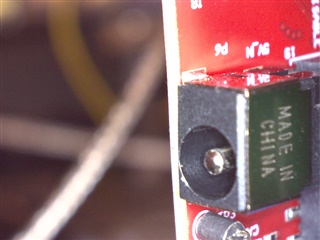
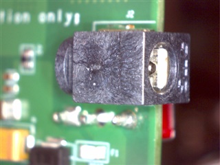
    However, I still have a questionable power connector, and I need the DCA so I can see the ADC data for my research.  It looks like I could wire across SW3 on the DCA, which should link the two power connectors together, and thereby power the whole thing via the DCA ... not a normal configuration. However, first I'd like some confirmation that this would be a safe thing to do - and that you agreed to this mod.  I reckon we have good indication that its all working OK, bar a duff connector, but just in case anything has to be returned! I've attached photos of the two connector designs, just so you know exactly what I have.

    Hopefully we're getting close! Soon, i'l need to know more about how to control the modules.  Is the API, commands etc (i.e. what's in the config file) documentation in there?  I have the SDK, toolbox etc.

    many thanks

    Alan

  • Alan,

    Glad to hear youre making progress. If you believe the device is faulty, I would recommend you talk to your local sales representative so that you can get that worked out. If the demo is outputting to the aux port, it is definitely safe to say that it is working properly. I will see if I can get someone who is a bit more familiar with the hardware to comment on whether there are any issues with your physical setup.

    Best Regards,
    Alec

  • Alan, 

    Sorry, forgot to comment on documentation. In terms of the basic out of box demo, all the CLI commands are documented in the SDK user guide section titled "Configuration File Format". This will explain what the basic parameters do. It is worth noting that many of our demos found in the Industrial or Automotive Toolbox may have their own new or modified cfg parameters for their specific use case or processing chain. Depending on what your end project is, it may be best to start with a lab/demo that accomplishes something similar.  You can also read more about the output format for the out of box demo at "<Industrial_Toolbox_Loc>\labs\out_of_box_demo\common\docs\understanding_oob_uart_data.html", again, this may change depending on the lab/demo. If you are just looking to capture raw data, then the DCA + mmwave studio approach is the best way forward.

    Best Regards,
    Alec

  • Alan,

    I got some feedback from someone else in my team and we have some additional questions/comments.

    What firmware are you using in mmWave Studio? It says there is a firmware mismatch in the log. You should be using the latest firmware from DFP 1.2.6.3 located at C:\ti\mmwave_dfp_01_02_06_03\rf_eval\rf_eval_firmware directory (assuming you're usingthe default install path).

    Also, you should set the switch SW2 to AWR1642_MODE for AWR1843.

    Best Regards,
    Alec

  • Hi Alec,

    well apart from a questionable power connector, it looks pretty much like the IWR is OK - DCA still to prove, though I guess. I know my supplier would have to defer to TI for a decision on returns (so this thread is useful as evidence of what we've tried so far), but its looking unlikely that  the IWR at least needs to go back - unless I could have one with a usable connector??

    I'l leave this thread open a little longer to see if anyone can confirm whether the DCA SW3 link & using the DCA power connector is OK to do.

    As for firmware & DFP things - I'll have to check and get back to you on that.

    many thanks for your help

    Alan

  • Alan,

    Of course! Someone else had mentioned to me that sometimes leaving DCA partially connected can cause some issues (I would presume related to power draw). But I think now that you have verified with OOTB demo, you can go back to trying to set up mmwave Studio and the DCA board for data capture. Let me know what you find when you get back to that point and try out the things we mentioned previously. 

    Best Regards,
    Alec

  • Hi Alec,

    a little further... I don't think its just a loading or PSU issue: the IWR OOBdemo does NOT work with the DCA attached (and independently powered). With the DCA, it goes well, but there's no data in the visualiser.  Disconnect DCA - A-OK!

    Next, I've gone for it an linked across DCA SW3, so that the two psu inputs are connected together - so I can now power the whole thing reliably using the DCA input - this is of course how I then found out the the OOBdemo doesn't work if you've got a DCA attached.  OK, the video for the demo doesn't show a DCA, so maybe fair enough!

    Back to mmWave Studio - it all connects and seems to set up, but still no data.  Having just remembered the OUTPUT tab, it gets to RFINIT and says:

    [14:29:03]  [RadarAPI]: Status: Failed, Error Type: RESP TIMEOUT

    so something still amiss there?

    You asked about mmWave studio firmware & DFP - I'm sure it'll be obvious, but where do I find out what its using?

    thanks

    Alan

  • Hi, 

    Yes, I believe some configuration may occur if the DCA is connected that can affect the running demo. It's important to remember that the DCA device is intended for data capture during development, and is not part of our normal ecosystem, so switching back and forth is not the typical use case. 


    In terms of firmware, towards the bottom of MMW studio you should see a file for "BSS FW", try updating this path to point to the file at 
    C:\ti\mmwave_sdk_03_05_00_04\firmware\radarss\xwr18xx_radarss_rprc.bin

    However, the error you posted above seems like a timeout during the process of connecting the device and EVM to each other. Could you possibly upload a picture of your physical setup? it may be easier to see all of your switches, cables, etc.

    Best Regards,
    Alec

  • Hi Alec,

    OK I see what info your looking for.  I've downloaded & used what I believe the instructions say to do, so got whatever versions came.  What I'm using now is:

    mmWave Studio 2.1.1.0
    C:\ti\mmwave_sdk_03_05_00_04\firmware\radarss\xwr18xx_radarss_rprc.bin
    C:\ti\mmwave_studio_02_01_01_00\rf_eval_firmware\masterss\xwr18xx_masterss.bin

    Seems that the SDK it gave me is newer that mmWave Studio?  I don't immediately see an SDK version for the masterss - don't know if this gives me a mismatch, and should I be looking for a newer mmWaveStudio to match the SDK?

    As far as physical setup goes - in all these things it would be much easier if you were sat here and could see exactly what I'm doing for yourself! Its all pretty much as you see in the demo videos - but there is one thing to consider.  My PC lives on the floor, the IWR etc on the bench above.  Many USB cables just aren't long enough, and I need more ports that the PC has. Thus I use an extender/hub thing - and mostly this works just fine. However, I know that the IWR USB doesn't like this (seems to work, but then hangs when downloading the firmware), so that one is now direct to the PC, but the DCA one is via the extender. This may also not like it very much! Now you'd think that USB cables were easy to come by, but I've struggled to get any from local outlets - even when the web says they've got them, they don't. So I've had to order up some longer ones so everything can go direct to PC ports.  These ought to be here on Friday. so probably best we wait for that and see if things improve.

    As for DCA switches, it says somewhere that SW2:5 should be set to configure_via_sw - does this override the other switch positions, especially SW2:3 for the LVDS mode? I think I sent you pictures of the DAC switches previously.

    thanks

    Alan

  • HI, Alan:

    The firmware version you are using looks fine to me.  There is no MSS binary in SDK you can use in mmwave studio.  It has to come from mmwave studio release.

    For the DCA1000 switch setting, please use the setting highlighted in the figure below. 

    For raw data capture, you can find some useful information at DCA1000 debug handbook.

    https://e2e.ti.com/support/sensors-group/sensors/f/sensors-forum/872161/faq-dca1000evm-dca1000evm-debug-resources

    Best,

    Zigang

  • Hi Zigang,

    thanks for the info: firmware etc versions OK - and DCA switch settings - done.  I've now got some better USB cables, so everything is direct to the PC, so shouldn't be any issues there. Everything seems to connect, but I'm still getting a time-out at RFINIT - and if I try sending another command, that times out too, so looks like it still alive but has got stuck, or has it died??  Windows still sees all the USB com ports, so they seems to be there still. OUTPUT details attached so you can see if I've done anything ion teh wrong order or missed anything.  I did note once, that it timed out downloading radarSS - only seen once though.

    That's enough for this week! Lets see if the weekend brings inspiration as to what to do next - and assuming of course that the most likely answer is on the lines of "user needs more training"!

    many thanks
    Alan

    GM: Constructor
    GM: Fri Aug 20 16:48:45 2021
    RSTD.Transmit("/Settings")
    [16:48:45]  
    [16:48:45]  ### Running Startup script: "C:\ti\mmwave_studio_02_01_01_00\mmWaveStudio\Scripts\Startup.lua" ###
    [16:48:46]  RSTD.SetAndTransmit ("/Settings/Scripter/Display DateTime" , "1")
    [16:48:46]  RSTD.SetAndTransmit ("/Settings/Scripter/DateTime Format" , "HH:mm:ss")
    [16:48:46]  Scripter ignored: Attempt to UnBuild() again or before Build.
    [16:48:46]  RSTD.SetVar ("/Settings/Clients/Client 0/Dll" , "C:\\ti\\mmwave_studio_02_01_01_00\\mmWaveStudio\\Clients\\\\LabClient.dll")
    [16:48:46]  RSTD.SetVar ("/Settings/Clients/Client 0/Use" , "TRUE")
    [16:48:46]  RSTD.SetVar ("/Settings/Clients/Client 1/Use" , "FALSE")
    [16:48:46]  RSTD.SetVar ("/Settings/Clients/Client 2/Use" , "FALSE")
    [16:48:46]  RSTD.SetVar ("/Settings/Clients/Client 3/Use" , "FALSE")
    [16:48:46]  RSTD.SetVar ("/Settings/Clients/Client 4/Use" , "FALSE")
    [16:48:46]  RSTD.SetVar ("/Settings/AL Client/AL Dll" , "C:\\ti\\mmwave_studio_02_01_01_00\\mmWaveStudio\\RunTime\\SAL.dll")
    [16:48:46]  RSTD.SetVar ("/Settings/Clients/Client 0/GuiDll" , "")
    [16:48:46]  RSTD.SetVar ("/Settings/AutoUpdate/Enabled" , "TRUE")
    [16:48:46]  RSTD.SetVar ("/Settings/AutoUpdate/Interval" , "1")
    [16:48:46]  RSTD.SetVar ("/Settings/Monitors/UpdateDisplay" , "TRUE")
    [16:48:46]  RSTD.SetVar ("/Settings/Monitors/OneClickStart" , "TRUE")
    [16:48:46]  RSTD.SetVar ("/Settings/Automation/Automation Mode" , "false")
    [16:48:46]  RSTD.Transmit("/")
    [16:48:46]  RSTD.SaveSettings(): Settings saved to "C:\Users\Alan_3_Normal\AppData\Roaming\RSTD\config.xml"
    [16:48:46]  RSTD.Build()
    [16:48:46]  RSTD.SaveSettings(): Settings saved to "C:\Users\Alan_3_Normal\AppData\Roaming\RSTD\config.xml"
    [16:48:46]  RSTD.Transmit("/")
    [16:48:46]  RSTD.AL_Build()
    [16:48:46]  RSTD.AL_LoadXml()
    [16:48:46]  RSTD.Transmit("/")
    [16:48:46]  RSTD.AL_Init()
    [16:48:46]  RSTD.Clients_Build()
    [16:48:46]  GM: Init
    [16:48:46]  GM: Loaded 'C:\ti\mmwave_studio_02_01_01_00\mmWaveStudio\Clients\\LabClient.dll'
    [16:48:46]  GM: 1 Guest (s) init
    [16:48:46]  GM: 1 Module(s) init
    [16:48:46]  GM: 2 Tab   (s) init
    [16:48:46]  RSTD.Client_LoadXml()
    [16:48:46]  [RadarAPI]: ar1.selectRadarMode(0)
    [16:48:46]  [RadarAPI]: Status: Passed
    [16:48:46]  Matlab Runtime Engine is installed
    [16:48:46]  [RadarAPI]: Starting Matlab Engine..
    [16:48:49]  [RadarAPI]: Matlab Engine Started!
    [16:48:51]  [RadarAPI]: ar1.selectCascadeMode(0)
    [16:48:51]  [RadarAPI]: Status: Passed
    [16:48:51]  [RadarAPI]: ar1.LoadSettings('C:\Users\Alan_3_Normal\AppData\Roaming\RSTD\ar1gui.ini')
    [16:48:51]  TESTING = false
    [16:48:51]  RstdNet: Port 2777: Listening..
    [16:48:51]  
    [16:48:51]  ***Script completed successfully.***
    [16:48:54]  [RadarAPI]: ar1.frequencyBandSelection("77G")
    [16:48:56]  [RadarAPI]: ar1.SelectChipVersion("AR1642")
    [16:48:56]  [RadarAPI]: Status: Passed
    [16:48:56]  [RadarAPI]: ar1.deviceVariantSelection("XWR1843")
    [16:48:56]  [RadarAPI]: Status: Passed
    [16:48:57]  [RadarAPI]: Opening Gpio Control Port()
    [16:48:57]  [RadarAPI]: Status: Passed
    [16:48:58]  [RadarAPI]: Opening Board Control Port()
    [16:48:58]  [RadarAPI]: Status: Passed
    [16:48:59]  [RadarAPI]: ar1.FullReset()
    [16:48:59]  [RadarAPI]: Status: Passed
    [16:49:00]  [RadarAPI]: Closing Board Control Port()
    [16:49:00]  [RadarAPI]: Status: Passed
    [16:49:00]  [RadarAPI]: Closing Gpio Control Port()
    [16:49:00]  [RadarAPI]: Status: Passed
    [16:49:00]  [RadarAPI]: ar1.SOPControl(2)
    [16:49:00]  [RadarAPI]: Status: Passed
    [16:49:07]  [RadarAPI]: ar1.Connect(27,115200,1000)
    [16:49:08]  [RadarAPI]: ar1.Calling_IsConnected()
    [16:49:10]  [RadarAPI]: ar1.SelectChipVersion("AR1642")
    [16:49:10]  [RadarAPI]: Status: Passed
    [16:49:10]  [RadarAPI]: ar1.SelectChipVersion("XWR1843")
    [16:49:10]  [RadarAPI]: Status: Passed
    [16:49:10]  Device Status : XWR1843/QM/SOP:2/ES:2
    [16:49:10]  [RadarAPI]: ar1.SaveSettings('C:\Users\Alan_3_Normal\AppData\Roaming\RSTD\ar1gui.ini')
    [16:49:15]  [RadarAPI]: ar1.DownloadBSSFw("C:\\ti\\mmwave_sdk_03_05_00_04\\firmware\\radarss\\xwr18xx_radarss_rprc.bin")
    [16:49:16]  [RadarAPI]: Downloading BSS Patch RPRC Binary..
    [16:49:23]  [RadarAPI]: ar1.GetBSSFwVersion()
    [16:49:23]  [RadarAPI]: BSSFwVersion:(02.00.00.01 (05/10/17))
    [16:49:24]  [RadarAPI]: ar1.GetBSSPatchFwVersion()
    [16:49:24]  [RadarAPI]: BSSPatchFwVersion:(01.02.06.11 (02/06/20))
    [16:49:26]  [RadarAPI]: ar1.DownloadMSSFw("C:\\ti\\mmwave_studio_02_01_01_00\\rf_eval_firmware\\masterss\\xwr18xx_masterss.bin")
    [16:49:27]  [RadarAPI]: Downloading MSS RPRC Binary..
    [16:49:37]  [RadarAPI]: ar1.GetMSSFwVersion()
    [16:49:37]  [RadarAPI]: MSSFwVersion:(01.02.05.02 (16/07/19))
    [16:49:45]  [RadarAPI]: ar1.PowerOn(0, 1000, 0, 0)
    [16:49:45]  [RadarAPI]: Status: Passed
    [16:49:45]  MSS power up done async event received!
    [16:49:49]  [RadarAPI]: ar1.SelectChipVersion("AR1642")
    [16:49:49]  [RadarAPI]: Status: Passed
    [16:49:49]  [RadarAPI]: ar1.SelectChipVersion("XWR1843")
    [16:49:49]  [RadarAPI]: Status: Passed
    [16:49:49]  Device Status : XWR1843/QM/SOP:2/ES:2
    [16:49:49]  [RadarAPI]: ar1.RfEnable()
    [16:49:49]  [RadarAPI]: Status: Passed
    [16:49:49]  BSS power up done async event received!
    [16:49:50]  [RadarAPI]: ar1.GetMSSFwVersion()
    [16:49:50]  [RadarAPI]: MSSFwVersion:(01.02.05.02 (16/07/19))
    [16:49:50]  [RadarAPI]: ar1.GetBSSFwVersion()
    [16:49:50]  [RadarAPI]: BSSFwVersion:(02.00.00.01 (05/10/17))
    [16:49:51]  [RadarAPI]: ar1.GetBSSPatchFwVersion()
    [16:49:51]  [RadarAPI]: BSSPatchFwVersion:(01.02.06.11 (02/06/20))
    [16:49:56]  [RadarAPI]: ar1.GetCaptureCardDllVersion()
    [16:49:56]  [RadarAPI]: Sending dll_version command to DCA1000
    [16:49:56]  [RadarAPI]: 
    [16:49:56]  DLL Version : 1.0
    [16:49:56]  [RadarAPI]: ar1.SelectCaptureDevice("DCA1000")
    [16:49:56]  [RadarAPI]: Status: Passed
    [16:49:58]  [RadarAPI]: ar1.CaptureCardConfig_EthInit("192.168.33.30", "192.168.33.180", "12:34:56:78:90:12", 4096, 4098)
    [16:49:58]  [RadarAPI]: ar1.CaptureCardConfig_Mode(1, 2, 1, 2, 3, 30)
    [16:49:58]  [RadarAPI]: ar1.CaptureCardConfig_PacketDelay(25)
    [16:49:58]  [RadarAPI]: Sending fpga command to DCA1000
    [16:49:58]  [RadarAPI]: 
    [16:49:58]  FPGA Configuration command : Success
    [16:49:58]  [RadarAPI]: Sending record command to DCA1000
    [16:49:58]  [RadarAPI]: 
    [16:49:58]  Configure Record command : Success
    [16:49:58]  [RadarAPI]: ar1.GetCaptureCardFPGAVersion()
    [16:49:58]  [RadarAPI]: Sending fpga_version command to DCA1000
    [16:49:58]  [RadarAPI]: 
    [16:49:58]  
    [16:49:58]  FPGA Version : 2.8 [Record]
    [16:49:58]  
    [16:50:11]  [RadarAPI]: ar1.ChanNAdcConfig(1, 1, 0, 1, 1, 1, 1, 2, 1, 0)
    [16:50:11]  [RadarAPI]: Status: Passed
    [16:50:17]  [RadarAPI]: ar1.RfLdoBypassConfig(0x1)
    [16:50:17]  [RadarAPI]: Status: Passed
    [16:50:19]  [RadarAPI]: ar1.LPModConfig(0, 0)
    [16:50:19]  [RadarAPI]: Status: Passed
    [16:50:21]  [RadarAPI]: ar1.SetMiscConfig(0)
    [16:50:21]  [RadarAPI]: Status: Passed
    [16:50:24]  [RadarAPI]: ar1.RfInit()
    [16:50:25]  [RadarAPI]: Status: Failed, Error Type: RESP TIMEOUT
    [16:50:33]  [RadarAPI]: ar1.LPModConfig(0, 0)
    [16:50:37]  [RadarAPI]: Status: Failed, Error Type: RESP TIMEOUT
    

  • HI, Alan:

    One question, are you manually program the radar studio through GUI?  Are these all default settings?   Or you are using some LUA script to automate this sequence of command?

    Best,

    Zigang

  • Hi Zigang,

    all entirely manual through mmWave GUI - and default settings, bar bypassing the LDO.

    thanks

    Alan

  • Why you choose to bypass LDO?  Can you try with bypass LDO disabled (as default)?

    Best,

    Zigang

  • Hi Zigang,

    I bypassed it because I thought I was supposed to, although the instructions around this aren't entirely clear.  It says that "if you are supplying 1V" .... now my board is REV-C; looking at the circuit around the relevant regulator it would appear to be set for 1V; the packaging of the IWR module says 1V on it, thus I selected the bypass.

    What I thought of as a check, is that the visualiser does eventually work (disconnect the DCA first) - I could see what commands it sends and then copy ... just because its at least something of the demos which has worked OK.

    I'll try this out and report back later today.

    many thanks

    Alan

  • Sure, please keep me updated. 

    Zigang

  • Hi Zigang,

    well.... the idea of looking at the comms for the Visualiser didn't help, it doesn't send this command!

    Now, going back over something from before: I had another look at the 5V supply, wondering if what its saying is that once things really get going, it takes more current ... and I definitely see the supply dip quite substantially at RF INIT.  Now, I already know that the power connector supplied on my IWR is terrible, you have to waggle it to work & then don't breathe.  However, maybe that's not the only problem here - so I looked more closely at the bench supply I'm using. Despite saying it should be up to the job, I've tried another one to be sure.

    No supply dip on the boards ... no time out and, eventually, I've got data captured and all the way through to the matlab screen!  I think we'll have to call that one-all for 5V issues - one dubious connector, and one dodgy bench unit!  Now, the real work starts...

    If you could give me some sort of confidence re whether I ought to be bypassing the LDO or not, the I think we're done. Once I have that info, I can close this thread.

    again, many thanks for your help getting things this far!!

    Alan

  • Hi, Alan:

    Great progress!   As I know if you are using a TI EVM board, you should use the default setting in LDO bypass in radar studio.   

    Best,

    Zigang