This thread has been locked.

If you have a related question, please click the "Ask a related question" button in the top right corner. The newly created question will be automatically linked to this question.

TDC1000: Regarding external clock for TDC1000-7200EVM

Part Number: TDC1000

Hello,

I am working on external clock to match two ultrasonic transducer (STEMINC) with the frequency of 3 MHz and 450 kHz.

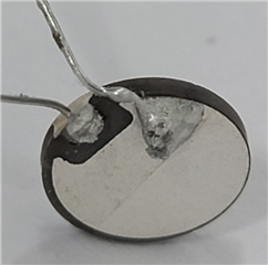
1) Name of model: SMD05T04R111WL and the spec is as follows.
- Dimensions: 5x0.4 mm
- Frequency: 450 kHz

2) Name of model: SMD063T07R111 and the spec is as follows.

- Dimensions: 6x0.7 mm

- Frequency: 3 MHz

To match them, I followed the previous instructions from the previous forum
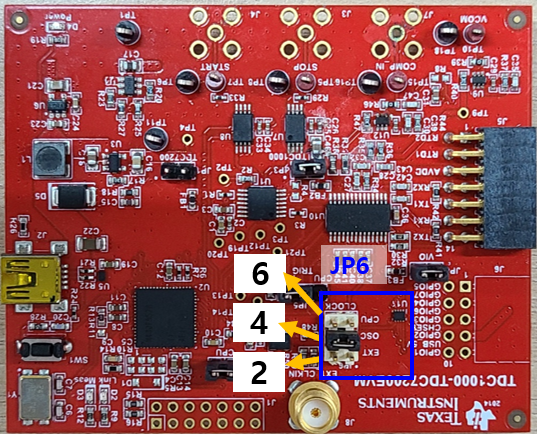
(https://e2e.ti.com/support/sensors-group/sensors/f/sensors-forum/1022935/tdc1000-transducer-change-and-related-issues-for-tdc1000-7200evm-module) but the GUI is stuck when I switch to external oscillator (waveform generator).

For SMD063T07R111 (3 MHz), I tried the below.

<Waveform generator setting>

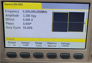
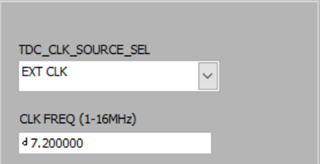
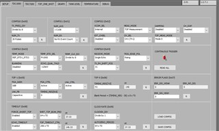
For TDC_CLK_SOURCE_SEL, I selected the external clock and put CLK_FREQ as same as waveform generator (6 MHz).
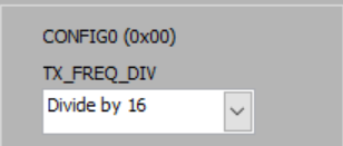
And for TX_FREQ_DIV, I selected "Divide by 2" so that I can match the frequency of transducer (6 MHz / 2 -> 3 MHz).

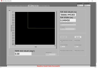
However, when I click  "START GRAPH", the GUI is stuck and doesn't show any data. 
I had to shut down the program. 


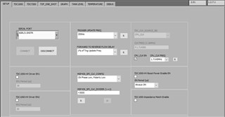
Could you please tell me what was wrong? I connected J8 to waveform generator with proper connector. 

Please let me know if more information is needed.

BR, 
Minrak Kim

  • Hi Minrak,

    Thank you for your question and the detailed setup. It sounds like the EVM is properly configured for 3MHz operation, I just want to verify everything matches on my end. Does your EVM have JP6 populated as the picture below illustrates? Additionally, is this 6MHz clock signal being driven through the J8 SMA connection?

    Assuming everything is proper, are you able to obtain accurate TOF measurements for the current setup using the “TOF_ONE_SHOT” measurement tab? This will help me understand if the issue is related to the graph portion of the GUI, or if the issue is somewhere else.


    Please let me know if you have any questions.

    Regards,

    Jacob

  • Hello, Jakob. 

    Thank you for your replies.

    I didn't know that I had to shunt JP6 for clock options. 
    So, for external clock, I need to populate as seen in your picture and I need to choose "CPU" for using CPU clock?
    And OSC means the clocking by the module, right?

    If there is anything wrong about what I understood, please give me correction.

    BR,

    Minrak Kim 

  • And I have one more question about shunting of JP6. 

    In the "TDC1000-TDC7200EVM User’s Guide" (as in left side of figure), "EXT_OSC" is done by shunting 2 and 1 in OSC_SOURCE_SEL.
    But what is written on the board is in the opposite order (From the top, it says top is ext, middle is OSC and bottom is CPU).

    To match with "TDC1000-TDC7200EVM User’s Guide", do I need to put the module upside down as in below?

    Please tell me which one is correct and I sincerely appreciate your past replies with picture illustration. 

    BR,
    Minrak Kim. 

  • Hi Minrak,

    Sorry for any confusion between the schematic and the User’s Guide instructions.

    For driving an external clock, populate a jumper in the JP6 row titled “EXT” (pins 1-2 on the EVM).

    You are correct in the orientation of the pins for the OSC_SOURCE_SEL. The EVM has the pins oriented upside down compared the EVM schematic.

    In this image, you have labeled the pin numbers correct. Another way to tell the numbering of pins is via the pin 1 indicator included in the top overlay of the EVM. I have highlighted the pin 1 indicator on the EVM picture with a yellow box. This pin 1 indicator will match with pin 1 of the schematic. Note, the jumper in this picture will need to be moved to pins 1-2 in order to externally drive a CLK. 

    Please let me know if you have any questions,

    Regards,

    Jacob

  • Thank you for your replies.

    Now I am trying to use SMD063T07R111 (3 MHz, 6 mm).

    As it is not soldered with wires, I tried soldering as in the picture below.

    However, it is not working properly. It is not problem of setting up the module ext. clock as 

    SMD05T04R111WL (0.45 MHz, with wires soldered already from Steminc) is properly working.


    I asked same question to Steminc and I am waiting for their answers.

    As you know well about the TDC1000 and related products in general, I asked you just in case.

    Please do take your time and give me advice if you have.

    BR,

    Minrak Kim

  • Hi Minrak,

    It is good to hear the clock is working properly. As for the piezo transducer, I would imagine the manufacturer will be better suited to answer your question.

    I did however find some content for best soldering practices when connecting to a piezo disk listed below:

    https://support.piezo.com/article/127-wiring-guidelines

    https://www.murata.com/en-us/support/faqs/sound/diaphragm/mnt/dm0001

    Please let me know if you have any other questions on the TDC1000

    Regards,

    Jacob

  • Hello,
    Thank you very much for your replies.

    When I tried to use CPU clock or EXT clock to match the transducer, I had to keep JP6 on "OSC" (Default, 5-4). 
    After switching JP6 to CPU or EXT clock (for EXT clock, J8 was connected properly to waveform generator with right signal),
    I cannot keep GUI generating any data.

    I used 450 kHz transducer and I did EXT to J8 but keep JP6 as "OSC"
    For 450 kHz, I did work.

    But when I keep JP6 to "EXT" as your recommendation or "CPU", it just stops. TOF_ONE_SHOT also doesn't work.

    What I don't really understand is that without changing JP6 to "EXT", "CPU" (keep JP6 to "OSC" no matter what), it still works and giving TOF signal (changing according to liquid level). 

    But I am suspicious of the absolute value of those results as it is not produced according to your (or TI's pdf) recommmendations.

    Do you have any suggestion for this result? I don't understand how it gives results without problem and why it stucks when I switch JP6.

    My best guess is there are other things in SW setup or other ports (other than JP6). 
    Here is what I changed.
    - "TDC_SOURCE_SEL" and CLK_freq for External waveform or CPU_CLK EN for CPU clock.
    Is there any more setting to be modified in GUI SW?

    I will appreciate your help and express thankfulness to what you have done to me.
    Please don't hesitate to give any question if you have. 

    BR, 
    Minrak Kim

  • Hello Minrak,


    Those are the primary settings I first use to setup an external clock.

    I am also surprised to hear the 8MHz internal OSC is giving a proper TOF measurement with a 450kHz transducer. For an 8MHz clk, the closest transmit frequency achievable is 500kHz with a divide by 16 in TX_FREQ_DIV.  

    What is your external clock frequency, and what is your TX_FREQ_DIV setting?


    These are possible settings below that would could be suitable for a 450kHz transducer with an external clock. 


    As another method for debugging, you could drive the external clock with 8MHz and see if the TOF measurements match the results using the oscillator.

    Please let me know if you have any questions,

    Regards,

    Jacob

  • Hello, 

    Thank you for your prelies.

    So let me summarize the results one more time. This time, lets discuss about "CPU" clock first. 
    In summary, chaning JP6 stucks GUI and I have to turn off the software.

    I used SMD10T2R111WL (10mm, 215 kHz). For this, settings for "setup", "TDC 1000", "TDC 7200" and "Tof-one=shot" are as follows.
    You can see that Tof-one=shot does not give any results as indicated by "NaN" (red mark). So "drive the external clock with 8MHz and see if the TOF measurements match the results using the oscillator" doesn't work for me as it just stucks. 

    <SETUP>

    <TDC 1000>

    <TDC 7200>


    <TOF-one-shot, JP6-"CPU">


    I said JP6 makes a problem because, when I do the same thing with JP6 on "OSC", it at leasts give me TOF value.
    All other settings are the same. 
    <TOF-one-shot, JP6-"OSC">

    But from your suggestions, it sounds like the module is not using CPU clock without changing JP6 to "CPU". Is that right?

    The same thing happens for "EXT" when I use waveform generator but lets discuss about CPU first as the settings look simpler. 

    Please don't hesitate to ask me you need more information.

    Best regards,
    Minrak Kim

  • Hello Minrak,

    Thanks for the pictures of your setup, and the error you are receiving. The GUI will seem to freeze because there is likely no transmit frequency (caused by the TDC1000 not receiving a clock) when you click "TOF_ONE_SHOT". 

    That is correct, the module will not use the CPU clock for the TDC1000 unless JP6 is set to CPU. Given your settings, the only way to receive "NaN" in CH1_Field is to select a CPU clock in the GUI, but set JP6 to "EXT". JP6 has the control of selecting which clock signal is used by the TDC1000, the GUI only configures the CPU clock and alters the GUI settings to reflect the utilized transmit freq. This is why the TOF measurement works when you move the jumper to "OSC", but not when you set JP6 to "EXT". The only way you could receive the "NaN" message in CH1_Field with JP6 set to "CPU" would be due to a damaged microcontroller. You could test this through probing JP6 with an oscilloscope. Another great method for debugging is to probe the transducer output with a scope probe for initial testing. Note, in some cases the probe can negatively affect the transmit and receive characteristics of the transducer due to the impedance of the probe.  

    Additionally, I do not think the current EVM settings will be optimal with a 215kHz transducer. I was able to replicate your settings with a similar transducer, and I was unable to receive a measurable return echo. I am including a document in this thread that will be very useful in reconfiguring the EVM settings for use with a 215kHz transducer (Link Here). See "TDC1000 220kHz Configuration" for a similar configuration to what you can use with your EVM.

    To use the 215kHz transducer, you will need to alter the GUI settings as suggested by the optimization application report, and change the external filters used by the TDC1000. The TDC1000 datasheet details the calculations for specific filter frequencies in section 8.3.5. (Datasheet Link Here).

    Please let me know if you have any questions.

    Thank you,

    Jacob