This thread has been locked.

If you have a related question, please click the "Ask a related question" button in the top right corner. The newly created question will be automatically linked to this question.

TDC1000: Regarding CPU or external clock for TDC1000-7200EVM

Part Number: TDC1000

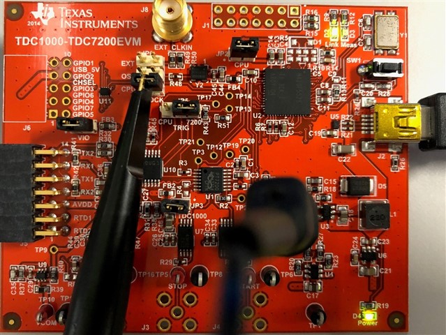
Hello, I am Minrak and working on TDC1000-7200 EVM module.

I have asked serial questions regarding the CPU or external clock in the previous post (https://e2e.ti.com/support/sensors-group/sensors/f/sensors-forum/1032912/tdc1000-regarding-external-clock-for-tdc1000-7200evm).

Still, I need help and please check the details of my situation in the previous post.

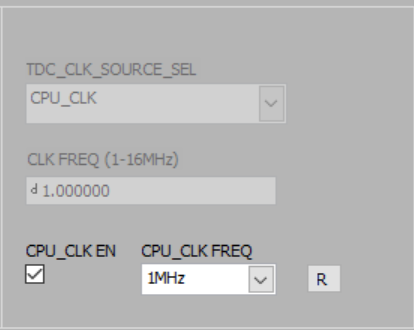
Regarding the last answer by "Jacob Nogaj", he mentioned "the module will not use the CPU clock for the TDC1000 unless JP6 is set to CPU. Given your settings, the only way to receive "NaN" in CH1_Field is to select a CPU clock in the GUI, but set JP6 to "EXT".

However, I did select CPU clock in GUI and set JP6 to "CPU". Whenever I set "JP6" to "CPU" or "EXT" to match GUI settings, it just stucks. GUI doesn't move and I need to shut down the program by force.

I followed everything correct as you see in the previous posts. 

Please help me so that I can use CPU or EXT clocks for transducers I am using.

Best regards,
Minrak Kim

  • Hello Minrak,

    I am sorry to hear the previous suggestions did not help to resolve your issue.


    I am going to start eliminating possible causes of error to determine where the issue may be. A starting point is making certain the clock is functioning as expected, I will use an oscilloscope to verify this.

    First, I am going to test the CPU clk option. I configure my board to look as the picture below displays (JP6 connects to CPU CLK):

    Then configure the GUI to include the CPU clock:

    Then Probe the testpoint on the CLK jumper to measure if the CPU clock is active

    Scope Waveform below:


    This test will verify if the clock is actively driving the EVM.

    Please let me know if your results look identical to mine. If so, we can continue to the next step in debugging why the EVM is not functioning as you expect.

    Please let me know if you have any questions.


    Thank you,

    Jacob

  • Hello, Jacob.


    Thank you very much for your illustration with pictures in detail. I have two questions as below.

    1. For probe location, can I locate GND of oscilloscope to any GND of the module? For (+) side probe, it seems to be on JP6-CPU in case of CPU clock.

    2. I will also try to measure raw data with oscilloscope for EXT clock as well. I will share the results for both CPU and EXT clocks.


    Lets say, I will use transducer with frequency of 3 MHz. As I know, the waveform generator can show as below.

    For frequency, I can divide 6 MHz with 2 to make 3 Mhz.

    But for amplitude and duty cycle, I am not sure what to input.
    2-1) Voltage can be 3.3 Vpp or 3.3 V rms or etc. Which one should I use?
    2-2) For duty cycle, what value is proper? I think the transducer will be greatly affected by the duty cycle. What do you suggest?

    Korea is on national vacation until next Wednesday so please understand me if I don't reply to your prospective answer for the previous question.
    I will be keeping up with your answer as soon as you upload your answer during holidays.


    I really appreciate your help. I will get back to you very soon.

    BR,
    Minrak Kim

  • Hi Minrak,

    1. You are correct, the probe is located on JP6-CPU, and the ground can be located on any test point ground.
    2. 3.3 VPP (0V low, 3.3V high) is the desired input to use for an external clock. The duty cycle should be set to 50%. I have never tried driving a non-50% duty cycle clock into the EVM, but it may contribute to error by using a non-50% duty cycle clock.


    Happy to help, let me know if you have any questions when you return from holiday.


    Regards,

    Jacob