This thread has been locked.

If you have a related question, please click the "Ask a related question" button in the top right corner. The newly created question will be automatically linked to this question.

TUSS4470: TUSS4470 Measuring Distance Problem

Part Number: TUSS4470

Hi,

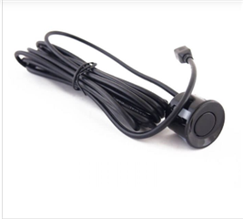
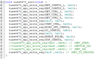
I am using TUSS4470 ultrasonic sensor for measuring distance but I couldn't manage to do that. This my init values 

I am generating 16 pulses with 40kHz frequency on TUSS4470 IO2 pin.

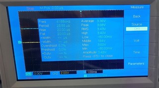
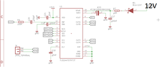
This is my schematic that I use. I am powering TUSS470 with 12V supply.

This is the write and read functions that I use and when I read the status register I get 0x08 value as return and as a datasheet this is the correct value.

void tuss4470_spi_read_reg(uint8_t register_value) {
memset(tx_buf,0x00,2);
memset(rx_buf,0x00,2);

register_value = 0x80 + ((register_value & 0x3F) << 1);

tx_buf[0] = register_value;
tx_buf[1] = 0x00;

HAL_GPIO_WritePin(NSS_PIN_GPIO_Port, NSS_PIN_Pin, GPIO_PIN_RESET);
HAL_Delay(15);
HAL_SPI_TransmitReceive(&hspi2, tx_buf,rx_buf, 2, 100);
HAL_GPIO_WritePin(NSS_PIN_GPIO_Port, NSS_PIN_Pin, GPIO_PIN_SET);
HAL_Delay(20);
}

void tuss4470_spi_write_reg(uint8_t register_value, uint8_t data_value) {
memset(tx_buf,0x00,2);
memset(rx_buf,0x00,2);

register_value = (register_value & 0x3F) << 1;
register_value |= tuss44x0_parity(&register_value); // apply parity bit

tx_buf[0] = register_value;
tx_buf[1] = data_value;

HAL_GPIO_WritePin(NSS_PIN_GPIO_Port, NSS_PIN_Pin, GPIO_PIN_RESET);
HAL_Delay(15);
HAL_SPI_TransmitReceive(&hspi2, tx_buf,rx_buf, 2, 100);
HAL_GPIO_WritePin(NSS_PIN_GPIO_Port, NSS_PIN_Pin, GPIO_PIN_SET);
//HAL_Delay(20);
}

and my main looks like this I use IOMODE 0 and I triggered CMD_TRIGGER bit.

int main(void)
{

HAL_Init();

SystemClock_Config();

MX_GPIO_Init();

MX_SPI2_Init();
MX_TIM3_Init();
MX_TIM21_Init();
MX_ADC_Init();


HAL_GPIO_WritePin(BOOST_EN_GPIO_Port, BOOST_EN_Pin, GPIO_PIN_SET);
HAL_Delay(1000);
HAL_ADC_Start(&hadc);

chip_id = get_chip_id();

HAL_TIM_Base_Start(&htim21);
tuss4470_init();
status = get_status();
HAL_TIM_IC_Start_IT(&htim3, TIM_CHANNEL_3);
HAL_Delay(1000);

status = get_status();

while (1)
{

tuss4470_spi_write_reg(TOF_CONFIG, 0x00);
delay_us(11);
tuss4470_spi_write_reg(TOF_CONFIG, 0x01);
delay_us(11);
generate_pulses();
tuss4470_spi_write_reg(TOF_CONFIG, 0x00);

HAL_Delay(100);

}

This is the signal when I read the OUTA pin. It is not changing at all when I changing the position of ultrasonic transducer .

This is the signal when I read the OUT3 pin. This signal isn't changing either.

These signals only change when I touch the ultrasonic transducer  and It looks like this when I touched it or pressed it.

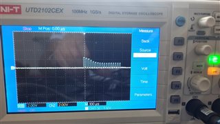
I tried to put 100 ohm resistor between OUTA and OUTB pin. Signals are changed but they still steady. This is the OUTA pin signal after when I put 100 ohm resistor.

Any help would be so appreciated. What do I do wrong? Is it the init function values or do I use wrong ultrasonic transducer? These signals that I read is the signals that I should read? 

Best regards.

  • Hello,

    Thank you for the detailed information on your application.

    Can you share the transducer as well as the register configuration settings you are using? This will help me understand more about how you have configured the device.

    I took a quick look at the schematic provided, and most seems proper. My only comment is to ensure proper grounding practices between the transducer GND and the analog GND:


    A lack of proper separation can significantly influence the receive signal amplitude. Note, you will not likely be able to probe Out A and see the return echo on an oscilloscope. In most cases the noise will make the echo only distinguishable after the internal amplification and filtering stages.  

    The 100-ohm resistor between OutA and OutB looks to be damping the response of the transducer excessively. We typically recommend using a potentiometer, or testing of various resistors to evaluate the optimal resistor for minimizing decay time.

    I will be able to more accurately understand where the problem may be with a further understanding of the configuration registers and the transducer part number.

    Please let me know if you have any questions.

    Thank you,

    Jacob

  • This is the transducer that I use

    This is the sensor overview

    Sensor Working Principle:

    • IO trigger through supplying at least 10us sequence of high level signal
    • The module automatically send eight 40kHz square wave and detect any response from the returning pulse signal
    • If there is signal returning, ECHO pin will pulse high. By calculating the difference in timing from sending to receiving and dividing by the speed of sound we will be able to get the distance of the object
    • Distance = duration / 2 / 29.1

    My register configuration settings in init function I assume that you wanted to me explain why I use these configuration settings so I'll explain.

    I gave BPF_CONFIG_1 to 0x00 value because I am generating 40kHz frequency pulses and I use band pass filter.

    I gave BPF_CONFIG_2 to 0x00 value because when I looked at this forum people use this configuration value for 40kHz frequency.

    This is the tricky part I've used different configuration values for DEV_CTRL_1 and DEV_CTRL_2. I am not sure that I use correct values of these registers I was hoping that someone helps me to choose right values.  For example in DEV_CTRL_2 register should I Disable first logamp stage to reduce quiescent current and disable last logamp stage quiescent current or should I enable it?

    In my current configuration settings in DEV_CTRL_1 register I set LOGAMP_FRC bit  and I use 0x4 = 2.6×VOUT_SCALE_SEL+3.94×VOUT_SCALE_SEL V/V for LOGAMP_SLOPE_ADJ and I use 0.931 for LOGAMP_INT_ADJ .

    In DEV_CTRL_3 Register I use 0x00 value because I am using IO0 mode. You can see the other configuration settings by looking at the datasheet.

    I actually need the be sure about my configuration settings If you help me about that that would be great. 


  • Hello Umut,

    Thank you for the additional information.

    For Dev_CTRL_1, it is fine to use 0x4 for the log amp. Sometimes the log amp requires tuning to obtain the proper dynamic range for the particular ultrasonic application. I recommend maintaining the current value for the time being, and we can look to see if altering this value improves performance in the future.

    Dev_CTRL_2 Is a register I might make changes to. I recommend enabling the first and last stage Log amp for testing purposes. Unless the application requires very low Iq, it is usually best to not disable some stages of the log amps. The LNA gain can also be an important field to adjust. I typically recommend starting at 15V/V for initial tests.

    Dev_CTRL_3 is set properly.


    Please let me know if you have any questions.

    Thank you,

    Jacob

  • Hello Jacob,

    Thank you for kind response and informations.

    What do you think about my other configuration values? I want to make sure that my all configuration values are correct that way I can focus on proper grounding and other stuff.

    Thank you.

  • Hello Umut,

    I am happy to review your other register settings.

    BPF is setup properly.

    DEV_CTRL was mentioned in previous post

    VDRV_CTRL VDRV is set to 10V, meaning your supply voltage must be atleast 10.3V to operate properly. It is also possible to turn off the regulation of VDRV by using 0x20 in the VDRV_CTRL register.

    Echo_INT_CONFIG is setup properly

    ZC_CONFIG may need adjustment. I think the threshold is too low for most applications. Try to use 0x14 for the register as a start, and adjust the threshold if necessary to improve performance.

    BURST_PULSE is currently setup for 0x16 which is 22 in decimal. This is a bit high for most applications. I recommend decreasing this number a bit for testing purposes. This value is dependent on many factors, so it is difficult to evaluate the best value without application level testing.

    TOF_CONFIG is setup properly


    Please let me know if you have any questions.


    Thank you,

    Jacob