Dear TI,
As you can read in my other (related) question I am working on developing software for use with the TMAG5273.
I’ve come quite far in the development, also thanks to Merke, and the communication works stable ad the sensor seems to work as expected until now.
First of all one strange thing I’ve noticed from the sensor is the following:
For the chip to work optimal for your needs you need to configure it using the writable registers 0x00 – 0x0C using the standard I2C write command from Figure 7-7.
The configurable registers 0x00 – 0x0C can’t be read-out using the 1-Byte I2C Read Command for 16-Bit data of figure 7-11 and 7-12. They can only be read out using the Standard 3-Byte I2C Read of figure 7-9 and 7-10.
Which one of the two read commands you can use to communicate with the chip is depended of the I2C_RD field of the DEVICE_CONFIG_1 register (one of the configurable registers).
The writing of the configuration registers doesn’t contain any CRC or checksum of some kind so to be sure the writing was done correctly you need to read out the registers you’ve written and check if they contain your values.
So in other words if you want to use the 1-Byte I2C Read Command for 16-Bit data of figure 7-11 and 7-12 you have to set the I2C_RD field (0x01) BUT you can never check if this was done correctly because for that you need to set the I2C_RD field to a different value (0x00). Is this correct or am I misinterpreting something?
I am just interested in the 16bits X, Y, Z. The quickest, and in my opinion the easiest, way to do this is to make use of the 1-Byte I2C Read Command for 16-Bit data of figure 7-11 and 7-12. I had implemented it this way but because I need robustness and the product I am developing must work at all times I chose to redo the work and just make use of the Standard 3-Byte I2C Read of figure 7-9 or 7-10. With this command you can read out, and validate, the configuration registers AND you can also read out the result registers 0x12 – 0x17 to get the 16bits X, Y, Z values.
Then the second strange thing came to light:
For the same robustness I was talking about earlier I implemented a CRC8 calculation and set the CRC_EN field of the DEVICE_CONFIG_1. Now if you are using the Standard 3-Byte I2C Read of figure 7-9 or 7-10 the TMAG5273 doesn’t support CRC if the data length is more than 4 bytes according to a note in the datasheet. (which doesn’t even seem to be true but later on more about that). For me I want to read-out 6bytes so I can’t get a CRC unless I chop the command in two and first read-out 5bytes (2byte X, 2byte Y and 1byte CRC) and then consecutively read-out 2bytes. Which costs way more time than just the simple 1-Byte I2C Read Command for 16-Bit data of figure 7-12 (with CRC). Again am I right or am I missing something?
Then a bit more of a technical question:
I configured the chip to be as follows using the packet structure shown in figure 7-7 (Standard I2C write):
Device Config1 (Address 0x00): 0xB4 (Crc enabled, TempCO = NdBFe, Con_Avg = 32X, I2C_RD = 3-byte read)
Device Config2 (Address 0x01): 0x12 (Low noise mode, Continuous measurment mode)
Sensor Config1 (Address 0x02): 0x70 (XYZ channels enabled)
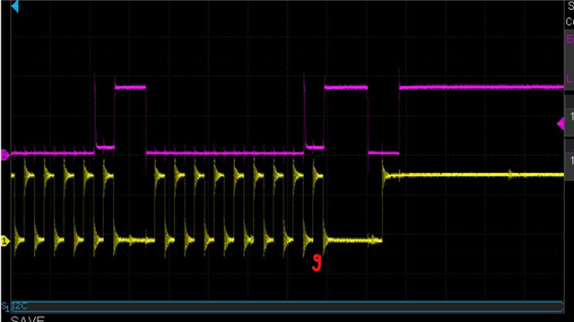
The message that I composed an wrote to the chip (confirmed using an oscilloscope):
| 0x6A | 0x80 | 0xB4 | 0x12 | 0x70 |
| AddressWrite| RegAddr 0x00 with trigger bit high | DeviceConf1 Data | DeviceConf2 Data | SensorConf1 Data |
Received an ack back on all bytes so everything OK
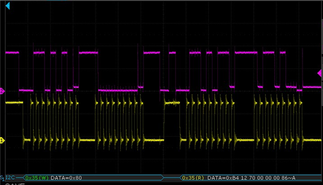
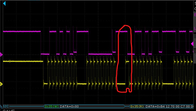
After that I try to read out the registers using the packet structure shown in figure 7-10 to confirm that the write was done correctly. I try and read 5 bytes as that is what the datasheet says you need to do to get a CRC back. What I expect to see on the oscilloscope:
| 0x6A | 0x80 | 0x6B | 0xB4 | 0x12 | 0x70 | 0x00 (reset value of register 0x03) | 0xC7 (CRC) |
Instead I see:
| 0x6A | 0x80 | 0x6B | 0xB4 | 0x12 | 0x70 | 0x00 | 0x00 (reset value of 0x04) |
If I try to read out 6 bytes, still no success.
| 0x6A | 0x80 | 0x6B | 0xB4 | 0x12 | 0x70 | 0x00 | 0x00 | 0x5B (CRC) |
What I get:
| 0x6A | 0x80 | 0x6B | 0xB4 | 0x12 | 0x70 | 0x00 | 0x00 | 0x00 (reset value of 0x05) |
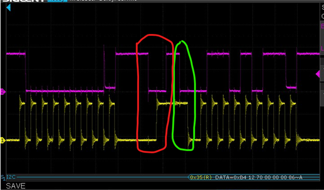
Only if I try to read out 7 bytes I get a CRC back
What I expect:
| 0x6A | 0x80 | 0x6B | 0xB4 | 0x12 | 0x70 | 0x00 | 0x00 | 0x00 | 0x86 (CRC) |
What I see:
| 0x6A | 0x80 | 0x6B | 0xB4 | 0x12 | 0x70 | 0x00 | 0x00 | 0x00 | 0x86 (CRC) |
Finally I received a CRC. What am I doing wrong?
Sincerely,
Tim von Unen