This thread has been locked.

If you have a related question, please click the "Ask a related question" button in the top right corner. The newly created question will be automatically linked to this question.

FDC2214: What's the ideal LC value of LC the LC tank for a capacitance range from 100pf to 500 pf?

Part Number: FDC2214

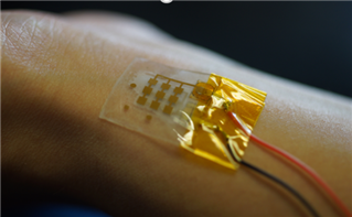
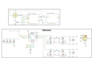
I have tried the default LC tank example for our blood pressure capacitance sensing application. 

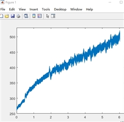
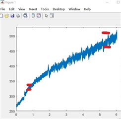
As attached picture the blood pressure capacitance amplitude becomes larger and larger, so I'm wondering if it has something to do with the LC tank value.

Our sensor's capacitance range is 100pf to 500pf. May I know if changing the LC tank value will help? And what's the exact L and C value you will suggest? Thanks!

  • Hi Patrick,

    Thank you for posting on the Position Sensing forum!

    Are you seeing this behavior when the system is in a constant state?

  • Hi! Yes. And we found that in lower capacitance range (around 30 pf) this behavior won't happen.

  • Hi Patrick,

    Your capacitance range is within the datasheet specifications, so I will need more information to help solve your problem.

    What inductor value are you using and what is your target frequency? Would it be possible for you to probe the device and confirm that the oscillation frequency is behaving as expected? Any screenshots you can provide would be helpful. 

    You mentioned this is for some kind of blood pressure application, is this device being used in its end application or is this a test circuit where the device is out in the open? Is the goal of this device to know when the blood pressure device comes in contact with the skin?

    Please provide any other details that might help me solve your problem. 

  • Hi! I'm not sure what you mean but the inductor value of the LC tank are same with the example. If you mean the frequency of my sensor then its 100kHz. The sampling rate is 75 Hz now.

    the attached are the unpressed and pressed sensor. Its a test circuit for our lab application and will be in clinical studies in the future, so its a big issue for us.

    The device is to measure the pulse waveform by capacitance sensor through bluetooth. Thanks! 

    unpress capacitance sensorPressed capacitance sensor

  • Hi Patrick,

    Thank you for for providing these waveforms! The waveforms for the unpressed and pressed sensor seem to be behaving as expected.

    I understand your frustration, but I need more context to be able to find you a solution. 

    • What are the units of the axes on the initial graph where you saw the unexpected behavior?
    • We have many examples for this device, can you show me the URL for the example you are referring to?
    • Can you send a schematic of your sensor setup?
    • Please attach a photo of your sensor setup and target.

    Answers to these questions will help me solve your problem. Thank you!

  • Hi! I'm wondering is it because when we press it the Vpp value becomes 200mV which is below the 1.2-1.8V the datasheet referred so the fdc works weird at this point?

    The X axes is just the time line and the Y axes is capacitance value from our sensor.

  • Hi Patrick,

    Thank you for helping me understand our concerns about the Vpp measurement. 

    I need more context to be able to find you a solution. 

    • We have many examples for this device, can you show me the URL for the example you are referring to?
    • Can you send a schematic of your sensor setup?
    • Please attach a photo of your sensor setup and target.

    Answers to these questions will help me solve your problem. Thank you!

  • Here's our sensor and the boards' schematic. We use a bluetooth chip for data communication. 

    For the setup, we put our sensor on wrist to measure the pulse (Capacitance variance) and the sensor is connected to the board.

    Thanks for helping!

  • Hi Patrick,

    Based on the information you provided, I feel like the issue might be due to EMI.

    Since this device is based on a resonant structure, it is very prone to electromagnetic interference. 

    What steps are you taking to shield this device from EMI? For some applications, extensive active shielding may be required. 

  • But its working well during low capacitance range. If its the EMI issue then the low capacitance range should also be affected? 

  • Hi Patrick,

    EMI is not constant and if it is effecting your reading at high capacitance it does not necessarily mean it will have the same effect at low capacitance. This is why shielding is very important to this device. What steps are you taking to shield this device from EMI?

    Another question is how are you measuring and changing the capacitance range from 100pF-500pF to 30pF?

    Can you post a picture of the electrodes that connect to the skin so we can get a better idea of your sensor?

  • I see. We use micro USB for the sensor side to board and Use a double layer board design to have bigger spaces for each component to reduce the EMI effects. Is there any suggestions?

    We use Iontronic materials for the dielectric so the capacitance will easy be changed from pf to nf.

    The picture is on the previous reply. Thanks!

  • Hi Patrick,

    On further reflection, it seems you are seeing some sort of drift which could be due to a number of factors including clock drift, drift in the parameters of the sensor that attaches to the skin, and EMI.

    For more information on this phenomenon, please search 'drift' on this forum and read the FAQ for this device. You can find some other useful information in an app note for a similar device.

  • Hi! I didn't mean the drift. I mean the distance between the red lines which is the amplitude of the pulse. Is it still the same reason of EMI? or How about the 1.2V -1.8V issue? Thanks!

  • Patrick,

    I have been working with Christen on your questions. 
    Christen mentioned drift because the amplitude you show seems to be growing without bound.
    If it wasn't drift, then the curve would increase - starting at 0 - grow, and then level off.
    But that doesn't seem to be happening here.

    Christen mentioned the factors that can contribute to drift.
    The next step involves some detective work and troubleshooting on your part.
    You will need to look (with measurements) at each of these factors to determine if they play a role.

    As Christen mentioned earlier, these devices are very sensitive to EMI.
    Applications using these devices usually require very solid shielding to avoid problems induced by EMI.
    Please keep that in mind in your investigation.

    We are closing this thread. 
    Once you have some measurements to share on potential clock drift, skin sensor parameter drift, and EMI, please feel free to post a new inquiry.

    Regards,
    John