Hello,
I was using MMWCAS-RF-EVM and MMWCAS-DSP-EVM for raw data capturing using mmwave studio 3.
I was confused about the frame definition of the MMWCAS-RF-EVM board. I created a post here, somehow I was not allowed to reply to that post any more.
I did more tests, it confused me more. Here are what I did.
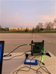
(1) Here is my test setup. The strong corner reflector was higher than the radar.
(2) I used the TI default given code below for processing the raw data.
C:\ti\mmwave_studio_03_00_00_14\mmWaveStudio\MatlabExamples\4chip_cascade_MIMO_example
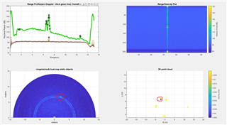
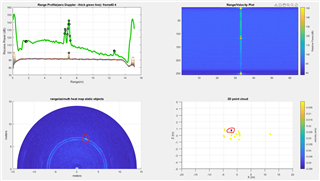
From above, I can see that the range-azimuth heatmap is consistent with the setup scene. The point cloud plot somehow is right-left flipped?
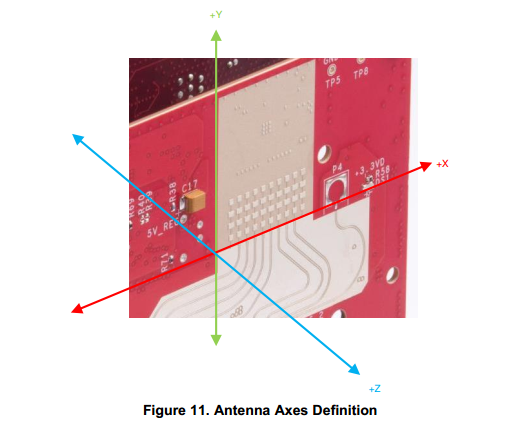
Other than that from my test, the radar forward is +Y, to right is +X, up is +Z.
However, the frame definition of "AWRx Cascaded Radar RF Evaluation Module.pdf" was given as below, which is absolute different.

My question are that
(1) Where is the origin point located on the RF board when the raw data was processed with the given code, namely 4chip_cascade_MIMO_example?
Is there any reference figures on how those 3D points were calculated?
(2) If the origin point is the same with Figure 11 above, how Figure 11 was related to the frame that being used for 4chip_cascade_MIMO_example?
Thanks a lot for the help!
Best,
Hang