This thread has been locked.

If you have a related question, please click the "Ask a related question" button in the top right corner. The newly created question will be automatically linked to this question.

IWR6843AOPEVM: mMwaveIcboost and DCA1000

Part Number: IWR6843AOPEVM
Other Parts Discussed in Thread: AWR1642, MMWAVEICBOOST, IWR6843AOP, IWR6843, DCA1000EVM

Hello Team,

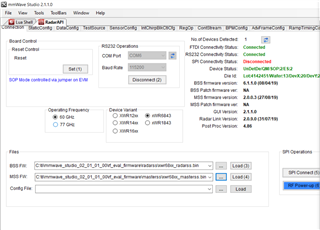
I have IWR6843AOPEVM with mounted on mmwaveboost and also connect with DCA1000 for raw data capture. I have few problems in regards this. First one is the connection between DCA1000 and mmwaveboost for 6843AOP. Other one to collect raw data but saves in form of CSV file. Can you help me in this regard Please?

Thank yoy

  • Hi Fahad,

    Please follow the instructions on this powerpoint:

    https://www.ti.com/lit/ml/spruik7/spruik7.pdf

    If it does not work, please reply with screenshots and every step taken. The DCA1000 board requires you to follow the sequence of steps relatively strictly.

    Best,

    Nate

  • Thank you for your kind reply. I thoroughly read the file but they used Awr1642. But I have IWR6842AOP. Is that work same as mentioned with other board becuase there is connection of MMwaveboost also involves.

    Thank you

  • Because I cannot find any specific rules for switches on DCA1000 or MMwaveicboost or on IWR6843AOP.

  • Hi Fahad,

    I believe you should still be able to get it working with the AOP board connected to the IC Boost connected to DCA1000. What part of the instructions are you stuck on?

    Best,

    Nate

  • Thank you for your kind reply. Following are the outputs from Mmwave studio when I click on Sp1 Connect and also it cannot show me the device status as I'm using IWR6843AOPEVM.

    Please help me in this regard. And also How I can capture raw data when I'm using vital sign demo Gui.

    Thank you

    GM: Constructor
    GM: Wed Jun 22 15:27:05 2022
    RSTD.Transmit("/Settings")
    [15:27:06]
    [15:27:06] ### Running Startup script: "C:\ti\mmwave_studio_02_01_01_00\mmWaveStudio\Scripts\Startup.lua" ###
    [15:27:06] RSTD.SetAndTransmit ("/Settings/Scripter/Display DateTime" , "1")
    [15:27:06] RSTD.SetAndTransmit ("/Settings/Scripter/DateTime Format" , "HH:mm:ss")
    [15:27:06] Scripter ignored: Attempt to UnBuild() again or before Build.
    [15:27:06] RSTD.SetVar ("/Settings/Clients/Client 0/Dll" , "C:\\ti\\mmwave_studio_02_01_01_00\\mmWaveStudio\\Clients\\\\LabClient.dll")
    [15:27:06] RSTD.SetVar ("/Settings/Clients/Client 0/Use" , "TRUE")
    [15:27:06] RSTD.SetVar ("/Settings/Clients/Client 1/Use" , "FALSE")
    [15:27:06] RSTD.SetVar ("/Settings/Clients/Client 2/Use" , "FALSE")
    [15:27:06] RSTD.SetVar ("/Settings/Clients/Client 3/Use" , "FALSE")
    [15:27:06] RSTD.SetVar ("/Settings/Clients/Client 4/Use" , "FALSE")
    [15:27:06] RSTD.SetVar ("/Settings/AL Client/AL Dll" , "C:\\ti\\mmwave_studio_02_01_01_00\\mmWaveStudio\\RunTime\\SAL.dll")
    [15:27:06] RSTD.SetVar ("/Settings/Clients/Client 0/GuiDll" , "")
    [15:27:06] RSTD.SetVar ("/Settings/AutoUpdate/Enabled" , "TRUE")
    [15:27:06] RSTD.SetVar ("/Settings/AutoUpdate/Interval" , "1")
    [15:27:06] RSTD.SetVar ("/Settings/Monitors/UpdateDisplay" , "TRUE")
    [15:27:06] RSTD.SetVar ("/Settings/Monitors/OneClickStart" , "TRUE")
    [15:27:06] RSTD.SetVar ("/Settings/Automation/Automation Mode" , "false")
    [15:27:06] RSTD.Transmit("/")
    [15:27:06] RSTD.SaveSettings(): Settings saved to "C:\Users\2332489A\AppData\Roaming\RSTD\config.xml"
    [15:27:06] RSTD.Build()
    [15:27:06] RSTD.SaveSettings(): Settings saved to "C:\Users\2332489A\AppData\Roaming\RSTD\config.xml"
    [15:27:06] RSTD.Transmit("/")
    [15:27:06] RSTD.AL_Build()
    [15:27:06] RSTD.AL_LoadXml()
    [15:27:06] RSTD.Transmit("/")
    [15:27:06] RSTD.AL_Init()
    [15:27:06] RSTD.Clients_Build()
    [15:27:06] GM: Init
    [15:27:06] GM: Loaded 'C:\ti\mmwave_studio_02_01_01_00\mmWaveStudio\Clients\\LabClient.dll'
    [15:27:06] GM: 1 Guest (s) init
    [15:27:06] GM: 1 Module(s) init
    [15:27:06] GM: 2 Tab (s) init
    [15:27:06] RSTD.Client_LoadXml()
    [15:27:07] [RadarAPI]: ar1.selectRadarMode(0)
    [15:27:07] [RadarAPI]: Status: Passed
    [15:27:07] Matlab Runtime Engine is installed
    [15:27:07] [RadarAPI]: Starting Matlab Engine..
    [15:27:25] [RadarAPI]: Matlab Engine Started!
    [15:27:30] [RadarAPI]: ar1.selectCascadeMode(0)
    [15:27:30] [RadarAPI]: Status: Passed
    [15:27:30] [RadarAPI]: ar1.LoadSettings('C:\Users\2332489A\AppData\Roaming\RSTD\ar1gui.ini')
    [15:27:31] TESTING = false
    [15:27:31] RstdNet: Port 2777: Listening..
    [15:27:31]
    [15:27:31] ***Script completed successfully.***
    [15:28:17] [RadarAPI]: Opening Gpio Control Port()
    [15:28:17] [RadarAPI]: Status: Passed
    [15:28:18] [RadarAPI]: Opening Board Control Port()
    [15:28:18] [RadarAPI]: Status: Passed
    [15:28:19] [RadarAPI]: ar1.FullReset()
    [15:28:19] [RadarAPI]: Status: Passed
    [15:28:20] [RadarAPI]: Closing Board Control Port()
    [15:28:20] [RadarAPI]: Status: Passed
    [15:28:20] [RadarAPI]: Closing Gpio Control Port()
    [15:28:20] [RadarAPI]: Status: Passed
    [15:28:20] [RadarAPI]: ar1.SOPControl(2)
    [15:28:20] [RadarAPI]: Status: Passed
    [15:28:45] [RadarAPI]: ar1.Connect(6,115200,1000)
    [15:28:48] [RadarAPI]: Error: Connection failed: Calling_ConnectTarget returned 3
    [15:28:48] [RadarAPI]: ar1.Calling_IsConnected()
    [15:28:48] [RadarAPI]: ar1.SaveSettings('C:\Users\2332489A\AppData\Roaming\RSTD\ar1gui.ini')
    [15:29:16] [RadarAPI]: ar1.frequencyBandSelection("60G")
    [15:29:19] [RadarAPI]: ar1.Connect(6,115200,1000)
    [15:29:21] [RadarAPI]: Error: Connection failed: Calling_ConnectTarget returned 3
    [15:29:21] [RadarAPI]: ar1.Calling_IsConnected()
    [15:29:21] [RadarAPI]: ar1.SaveSettings('C:\Users\2332489A\AppData\Roaming\RSTD\ar1gui.ini')
    [15:30:00] [RadarAPI]: ar1.Connect(6,115200,1000)
    [15:30:02] [RadarAPI]: Error: Connection failed: Calling_ConnectTarget returned 3
    [15:30:02] [RadarAPI]: ar1.Calling_IsConnected()
    [15:30:02] [RadarAPI]: ar1.SaveSettings('C:\Users\2332489A\AppData\Roaming\RSTD\ar1gui.ini')
    [15:30:38] [RadarAPI]: Opening Gpio Control Port()
    [15:30:38] [RadarAPI]: Status: Passed
    [15:30:39] [RadarAPI]: Opening Board Control Port()
    [15:30:39] [RadarAPI]: Status: Passed
    [15:30:40] [RadarAPI]: ar1.FullReset()
    [15:30:40] [RadarAPI]: Status: Passed
    [15:30:40] [RadarAPI]: Closing Board Control Port()
    [15:30:40] [RadarAPI]: Status: Passed
    [15:30:41] [RadarAPI]: Closing Gpio Control Port()
    [15:30:41] [RadarAPI]: Status: Passed
    [15:30:41] [RadarAPI]: ar1.SOPControl(2)
    [15:30:41] [RadarAPI]: Status: Passed
    [15:30:42] [RadarAPI]: ar1.Connect(6,115200,1000)
    [15:30:44] [RadarAPI]: Error: Connection failed: Calling_ConnectTarget returned 3
    [15:30:44] [RadarAPI]: ar1.Calling_IsConnected()
    [15:30:44] [RadarAPI]: ar1.SaveSettings('C:\Users\2332489A\AppData\Roaming\RSTD\ar1gui.ini')
    [15:32:28] [RadarAPI]: Opening Gpio Control Port()
    [15:32:28] Status: Failed to open/close GpioControl, Error Type: PROTOCOL ERROR
    [15:32:29] [RadarAPI]: Opening Board Control Port()
    [15:32:29] [RadarAPI]: Status: Failed to open/close BoardControl, Error value: -1
    [15:32:30] [RadarAPI]: ar1.FullReset()
    [15:32:30] [RadarAPI]: Status: Failed To give full reset, Error Value: -7
    [15:32:30] [RadarAPI]: ar1.SOPControl(2)
    [15:32:30] [RadarAPI]: Status: Passed
    [15:32:38] [RadarAPI]: ar1.Connect(6,115200,1000)
    [15:32:41] [RadarAPI]: Error: Connection failed: Calling_ConnectTarget returned 3
    [15:32:41] [RadarAPI]: ar1.Calling_IsConnected()
    [15:32:41] [RadarAPI]: ar1.SaveSettings('C:\Users\2332489A\AppData\Roaming\RSTD\ar1gui.ini')
    [15:32:43] [RadarAPI]: Opening Gpio Control Port()
    [15:32:43] [RadarAPI]: Status: Passed
    [15:32:44] [RadarAPI]: Opening Board Control Port()
    [15:32:44] [RadarAPI]: Status: Passed
    [15:32:45] [RadarAPI]: ar1.FullReset()
    [15:32:45] [RadarAPI]: Status: Passed
    [15:32:45] [RadarAPI]: Closing Board Control Port()
    [15:32:45] [RadarAPI]: Status: Passed
    [15:32:45] [RadarAPI]: Closing Gpio Control Port()
    [15:32:45] [RadarAPI]: Status: Passed
    [15:32:45] [RadarAPI]: ar1.SOPControl(2)
    [15:32:46] [RadarAPI]: Status: Passed
    [15:32:49] [RadarAPI]: ar1.Connect(6,115200,1000)
    [15:32:51] [RadarAPI]: Error: Connection failed: Calling_ConnectTarget returned 3
    [15:32:51] [RadarAPI]: ar1.Calling_IsConnected()
    [15:32:51] [RadarAPI]: ar1.SaveSettings('C:\Users\2332489A\AppData\Roaming\RSTD\ar1gui.ini')
    [15:38:44] [RadarAPI]: Opening Gpio Control Port()
    [15:38:44] Status: Failed to open/close GpioControl, Error Type: PROTOCOL ERROR
    [15:38:45] [RadarAPI]: Opening Board Control Port()
    [15:38:45] [RadarAPI]: Status: Failed to open/close BoardControl, Error value: -1
    [15:38:46] [RadarAPI]: ar1.FullReset()
    [15:38:46] [RadarAPI]: Status: Failed To give full reset, Error Value: -7
    [15:38:46] [RadarAPI]: ar1.SOPControl(2)
    [15:38:46] [RadarAPI]: Status: Passed
    [15:38:48] [RadarAPI]: Opening Gpio Control Port()
    [15:38:48] Status: Failed to open/close GpioControl, Error Type: PROTOCOL ERROR
    [15:38:49] [RadarAPI]: Opening Board Control Port()
    [15:38:49] [RadarAPI]: Status: Passed
    [15:38:50] [RadarAPI]: ar1.FullReset()
    [15:38:50] [RadarAPI]: Status: Passed
    [15:38:50] [RadarAPI]: Closing Board Control Port()
    [15:38:50] [RadarAPI]: Status: Passed
    [15:38:50] [RadarAPI]: ar1.SOPControl(2)
    [15:38:50] [RadarAPI]: Status: Passed
    [15:38:52] [RadarAPI]: Opening Gpio Control Port()
    [15:38:52] Status: Failed to open/close GpioControl, Error Type: PROTOCOL ERROR
    [15:38:52] [RadarAPI]: Opening Board Control Port()
    [15:38:52] [RadarAPI]: Status: Failed to open/close BoardControl, Error value: -1
    [15:38:53] [RadarAPI]: ar1.FullReset()
    [15:38:53] [RadarAPI]: Status: Failed To give full reset, Error Value: -7
    [15:38:54] [RadarAPI]: ar1.SOPControl(2)
    [15:38:54] [RadarAPI]: Status: Passed
    [15:38:56] [RadarAPI]: Opening Gpio Control Port()
    [15:38:56] [RadarAPI]: Status: Passed
    [15:38:57] [RadarAPI]: Opening Board Control Port()
    [15:38:57] [RadarAPI]: Status: Passed
    [15:38:58] [RadarAPI]: ar1.FullReset()
    [15:38:58] [RadarAPI]: Status: Passed
    [15:38:58] [RadarAPI]: Closing Board Control Port()
    [15:38:58] [RadarAPI]: Status: Passed
    [15:38:58] [RadarAPI]: Closing Gpio Control Port()
    [15:38:58] [RadarAPI]: Status: Passed
    [15:38:58] [RadarAPI]: ar1.SOPControl(2)
    [15:38:58] [RadarAPI]: Status: Passed
    [15:39:00] [RadarAPI]: Opening Gpio Control Port()
    [15:39:00] [RadarAPI]: Status: Passed
    [15:39:01] [RadarAPI]: Opening Board Control Port()
    [15:39:01] [RadarAPI]: Status: Passed
    [15:39:02] [RadarAPI]: ar1.FullReset()
    [15:39:02] [RadarAPI]: Status: Passed
    [15:39:03] [RadarAPI]: Closing Board Control Port()
    [15:39:03] [RadarAPI]: Status: Passed
    [15:39:03] [RadarAPI]: Closing Gpio Control Port()
    [15:39:03] [RadarAPI]: Status: Passed
    [15:39:03] [RadarAPI]: ar1.SOPControl(2)
    [15:39:03] [RadarAPI]: Status: Passed
    [15:39:04] [RadarAPI]: ar1.Connect(6,115200,1000)
    [15:39:05] [RadarAPI]: ar1.Calling_IsConnected()
    [15:39:06] Device Status : UnDetDe/QM/SOP:2/ES:2
    [15:39:06] [RadarAPI]: ar1.SaveSettings('C:\Users\2332489A\AppData\Roaming\RSTD\ar1gui.ini')
    [15:40:04] [RadarAPI]: ar1.DownloadBSSFw("C:\\ti\\mmwave_studio_02_01_01_00\\rf_eval_firmware\\radarss\\xwr68xx_radarss.bin")
    [15:40:04] [RadarAPI]: Downloading BSS ROM RPRC Binary..
    [15:40:52] [RadarAPI]: ar1.GetBSSFwVersion()
    [15:40:52] [RadarAPI]: BSSFwVersion:(06.01.01.00 (08/04/19))
    [15:46:28] [RadarAPI]: ar1.DownloadMSSFw("C:\\ti\\mmwave_studio_02_01_01_00\\rf_eval_firmware\\masterss\\xwr68xx_masterss.bin")
    [15:46:28] [RadarAPI]: Downloading MSS RPRC Binary..
    [15:46:47] [RadarAPI]: ar1.GetMSSFwVersion()
    [15:46:47] [RadarAPI]: MSSFwVersion:(02.00.00.03 (27/08/19))
    [15:48:57] [RadarAPI]: ar1.PowerOn(0, 1000, 0, 0)
    [15:48:57] Status: Failed, Error Type: RESP TIMEOUT
    [15:49:01] MSS Power Up async event was not received!
    [15:49:50] [RadarAPI]: ar1.PowerOn(0, 1000, 0, 0)
    [15:49:50] Status: Failed, Error Type: RESP TIMEOUT
    [15:49:54] MSS Power Up async event was not received!

  • Yes EVM in flashing mode because I want to capture some raw data from it.

  • Can you try mmwave studio version 2.1.0. This is the version I use.

    Additionally, is this problem replicable every time? This thread suggests resetting the device before operation, which seems to have worked for them.

    https://e2e.ti.com/support/sensors-group/sensors/f/sensors-forum/744606/awr1243boost-spi-connect-resp-timeout-issue-in-mmwave-studio-with-a-dca1000evm

    Best,

    Nate

  • Thank you nathan for your help. I have mmwave_studio_02_01_01_00 this version. But I think you cannot understand my question.

    Actually when I connect both devices it work well I can capture the bin file but the problem here is that after starting the gui of Vital sign it cannot started and give me the error as mentioned earlier. So how I can collect vital sign raw data.

    Regards,

    Fahad

  • Hi Fahad,

    Can you please explain to me what you mean by "vital sign raw data". Are you looking for the raw ADC data from the vital signs lab or for vital signs data (i.e. heart rate, breath rate).

    Thank you,

    Angie 

  • Hi Angie,

    Thank you for your reply on it. I want to capture RAW data from vital sign lab (Heart and Breath rate) for future post processing. I mean that when I start the vital sign lab so at the same time the raw data from heart rate and breath rate from sensors will saved in csv file on the same time. So I can use this raw data for Signal processing.

    Thank you,

    Fahad

  • Hi Fahad,

    Here are the IWR6843 specific instructions for raw data capture: /cfs-file/__key/communityserver-discussions-components-files/1023/0572.mmWave_5F00_sensor_5F00_raw_5F00_data_5F00_capture_5F00_using_5F00_DCA1000_5F00_xwr6843.pdf 

    As far as running this and the vital signs demo at the same time, this is possible but may require some development in CCS. Raw data capture is done over LVDS and, as I'm sure you know, the lab runs off the UART data. If you can get UART and LVDS running at the same time this is possible and if you have any questions on how to implement this feel free to ask here or in a new thread (whatever is easier for you!)

    (more on implementation of LVDS at file:///C:/<SDK DOWNLOAD LOCATION>/mmwave_sdk_03_05_00_04/packages/ti/demo/xwr68xx/mmw/docs/doxygen/html/struct_mmw_demo___lvds_stream_cfg__t.html#details)

    Thanks,

    Angie

  • Thank you angie for your help but this should be done once I am able to connect with spi connect switch which is not possible it gives me error on mmwave studio

  • Hi Fahad,

    I agree, are you still recieving the same error on mmwave studio after following the IWR6843 instructions I linked in my last reply? 

    I am going to look into the error you mentioned above on 6/22 for now.

    Thank you,

    Angie

  • Hi Angie,

    Thank you very much for your help. Yes I'm now able to connect my device both are working and fine now. And the data is captured as mentioned in the above pdf file.

    Now please help me as well I want to capture Raw ADC data of breath and heart rate. So at this stage it is possible to flash and functional the device because the sop and mux switches are changed due to DCA1000 connection.

    Kind regards,

    Fahad 

  • Hi Fahad,

    I am glad that it is working!

    Adding raw ADC collection to the vital signs lab will require modifying the project in CCS. You will need to add LVDS support so that you can collect raw data over LVDS while using the visualizer over UART. Is this what you are interested in doing?

    Thanks,

    Angie

  • Can you please share with me any documentation regarding this? Because I'm confuse so that switches will be in flashing or functional mode? And also share with me any matlab script for reading .bin file as well.

    Thank you

    fahad

  • HI, Fahad:

    The SDK OOB demo support raw data capture, and you can read section 3. 3. 2. mmWave demo with LVDS-based instrumentation in the SDK users guide.   You can read through the code to find how the data transfer through LVDS is made possible in the mmwave SDK demo.   After that, you can start to change the vital sign demo code to add this feature.   It may not be trivial. 

    On the other hand, you can find the executable code that configure and enable capture for DCA1000 at: C:\ti\mmwave_studio_02_01_01_00\mmWaveStudio\ReferenceCode\DCA1000

    Best,

    Zigang

  • Hi Zigang,

    I think you cannot understand my question as well. The main things are the Sop jumpers for CCS I remove SOP2 so its work. But when I connect Sop1 for Mmwave studio so ccs not working so how I can able to get raw data over LVDS?

    Thank you

    Fahad 

  • At one time only one thing connect CCs and mmwave studio both cannot work together. Is there any option so we can use only one of them and get raw data.

    Thank you

    Fahad

  • At one time only one thing connect CCs and mmwave studio both cannot work together. Is there any option so we can use only one of them and get raw data.

    Thank you

    Fahad

  • HI, Fahad:

    Mmwave Studio can not work together with any demo binary.   When running OOB demo for raw data capture, you can not use radar studio GUI any more.  You can flash the OOB demo binary (or connnect CCS) and run in the demo mode.  Then running DCA1000 CLI command in a cmd window to control DCA1000, please see mmwave_studio_user_guide.pdf section 3.1 for the information.   

    Best,

    Zigang

  • Hi Fahad,

    To further clarify, you can still capture raw data just not using mmwavestudio. 

    On top of that, you would need to add LVDS support to the project itself. This involves a lot of development in ccs.

    Thank you,

    Angie

  • Hi Angie,

    I hope you are doing well. Sorry for bother you again can you please share with that when raw data was stored .bin file so is there any thing about Timestamp because this aspect is more important.

    Looking forward to hear from you soon.

    Best wishes, 

    Fahad

  • Hi Fahad,

    Nice to hear from you! Are you asking if the raw data includes time stamp information?

    Thanks,

    Angie

  • Hi Angie,

    Yes. Any timestamp information it is better to have with raw data.

    Best wishes,

    Fahad

  • Hi, Fahad:

    There is a capture log file xxx_Raw_LogFile.csv, that contains the capture starting time stamp in second.  See the highlight in the following example:

    Start record configuration :
    ,
    Log mode : Raw
    LVDS lane mode : 2 lane
    Record stop mode : Infinite
    Max file size (MB) : 1024,
    ,*DT 1,
    ,5589584,176176,
    ,9871680,43680,
    ,15708784,14560,
    ,44974384,72800,

    Raw Data :
    Out of sequence count - 4
    Out of sequence seen from 30889 to 30940
    First Packet ID - 1
    Last Packet ID - 36009
    Number of received packets - 35798
    Number of zero filled packets - 211
    Number of zero filled bytes - 307216
    Capture start time - Tue Apr 12 14:15:23 2022
    Capture end time - Tue Apr 12 14:15:29 2022
    Duration(sec) - 6

    Best,

    Zigang

  • Thank you for your response. But where is the logfile located and how I can correlate the timestamp with the raw data.

    Regards,

    Fahad

  • Dear Zigang,

    I'm totally confused, because in pdf files it shows capture raw data by using mmwavestudio by doing settings etc. But you told me that mmwavestudio is not used to capture raw data or used CLI command. How can we set the frame number, chirp etc in CLI command. Then why mmwave stuido software is available for RF evaluation if we cannot capture data through it or it cannot work with sensor start demo.

    Please help me in this regard,

    Best regards,

    Fahad 

  • And also I got that from https://e2e.ti.com/support/sensors-group/sensors/f/sensors-forum/856054/faq-raw-adc-data-capture-from-mmwave-sensor 

    "We would recommend using mmWave Studio with DCA1000EVM/TSW1400 to capture the ADC data and follow mmWave Studio user guide & DCA1000_Quick_Start_Guide.pdf for the steps to do that".

    So how it works both demo and mmwavestudio at same time..

  • Hi Angie,

    Can you help me in your post as mentioned raw data over LVDS and Visualizer over UART. I'm interested in that. Please help me in this how I can do that.

    Regards,

    Fahad

  • HI, Fahad:

    This log file is located at the same directory as your captured binary file.  

    Best,

    Zigang

  • HI, Fahad:

    We always suggested to use mmwave studio for raw data capture.   But mmwave studio does not work with demo binary and you insist that you want to add capture feature into a demo code.   That is why we started this discussion on how you can follow SDK OOB demo + DCA1000 CLI for raw data capture.   The profile/chirp/frame configuration is all programmed through configuration file for the OOB demo.   For example, you can search profileCfg in SDK users guide. 

    Best,

    Zigang


  • Ok I understand but I got an error of invalid configuration. in OOB demo visualizer.

  • Hi Fahad,

    Can you please share more details on this error?

    Thank you,

    Angie