Other Parts Discussed in Thread: TDC7200
Hi !
I'm Trieu Le from RYNAN Technologies Vietnam.
I have some questions about TDC1000 and TDC7200 drivers, please let me clearly understand about it.
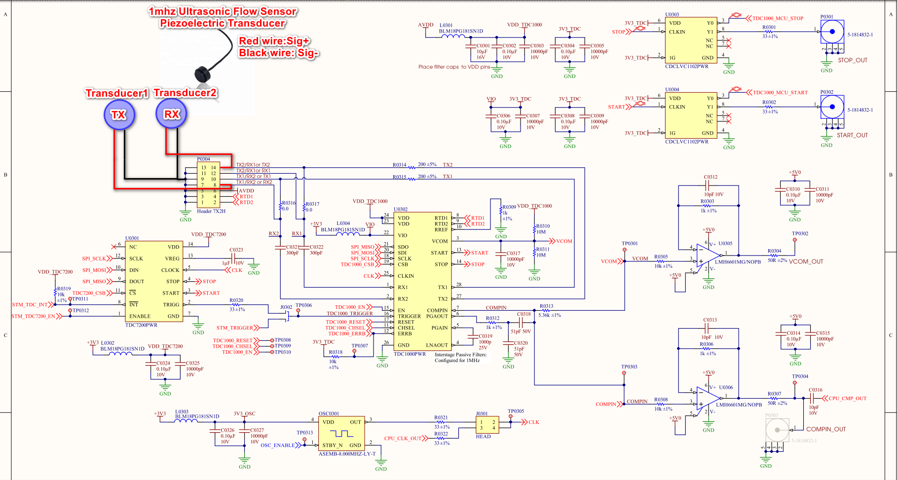
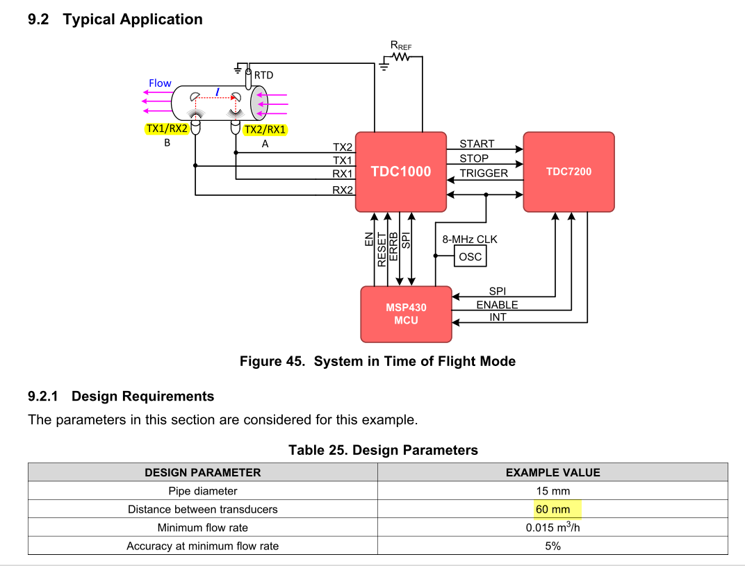
We have followed the reference design from TI based on TDC1000-TDC7200EVM development KIT.
And using 1 MHz transducer for our application, here is it: https://www.everychina.com/p-z52fca17-110907690-piezoelectric-transducer-micro-1mhz-ultrasonic-flow-sensor.html
In our application we want to install 2 transducers fixed about 0.5 meters apart, both of them submerged underwater. We want to measure the Transit-Time between 2 transducers.
Is this design suitable for our application?
Here are some questions I need your help:
- I want to use 2 transducers to measure the Transit-Time between 2 transducers, which mode should be configured for TDC1000 in this case?
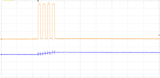
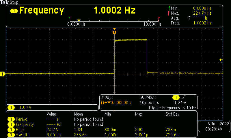
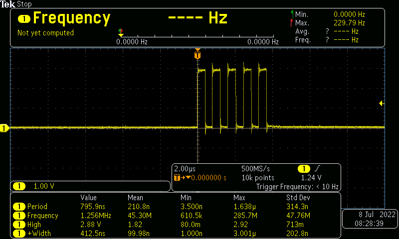
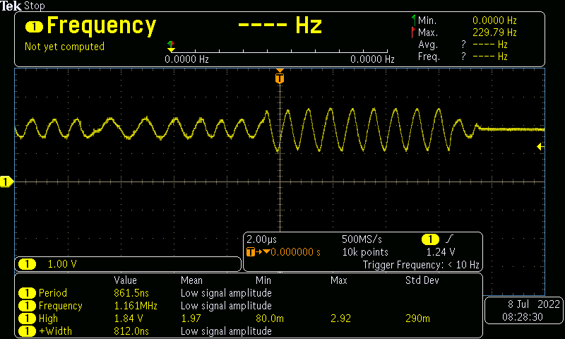
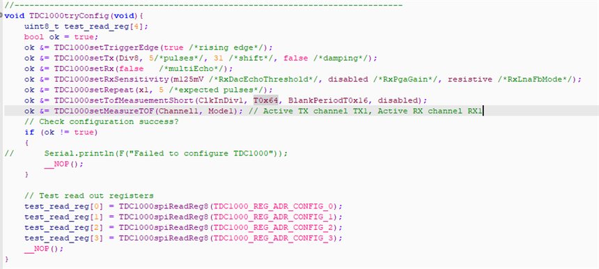
- I also tried to config TDC1000 working in mode 1 and channel 1 (Active TX Channel is TX1, Active RX Channel is RX1) then I connected only 1 transducer to RX1 pin, make pulse to TRIGGER pin every 1 second and I got the STOP pulses, and also got the waveform from COMPIN pin. My question is: Why is there a signal when I have only connected 1 transducer to pin RX1 (Pin TX1 is No Connected)
- Is this 1MHz transducer and this design suitable for Transit-Time measurements underwater?
Thanks !