This thread has been locked.

If you have a related question, please click the "Ask a related question" button in the top right corner. The newly created question will be automatically linked to this question.

DCA1000EVM: DCA1000EVM + IWR6843ISK for Raw Data Capture for Area scanner Lab: Unable to connect mmwave studio

Part Number: DCA1000EVM
Other Parts Discussed in Thread: IWR6843ISK, UNIFLASH, IWR6843, IWR1843BOOST

Hello, 

I am trying to connect DCA1000EVM + IWR6843ISK EVM board for RAW Data capturing. 

Installed softwares as below: 

No 

Software Name 

Version 

1 

Uniflash  

Version: 7.1.0.3796 

2 

Code Composer Studio 

Version: 8.3.1.00004 

3 

MmWave SDK  

mmwave_sdk_03_05_00_04-Windows-x86-Install.exe 

4 

MMWAVE industrial Toolbox  

  ??

5 

MMWave studio 

Version 2.1.1.0 

Steps I followed: 

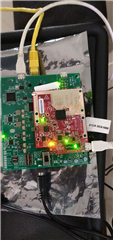
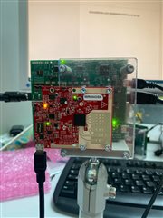
Connected the Hardware DCA1000EVM + IWR6843ISK EVM as below: for AREA SCANNER lab

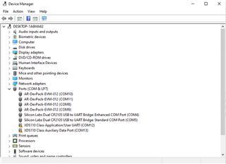
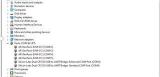
Able to see the ports in the Device manager like below : 

I followed the DCA1000 training video : https://training.ti.com/dca1000-training-video and pdf:  https://training.ti.com/sites/default/files/docs/mmwave_sensor_raw_data_capture_using_dca1000_v02.pdf : I am not understanding what is the next step after checking the ports in Device manager. 

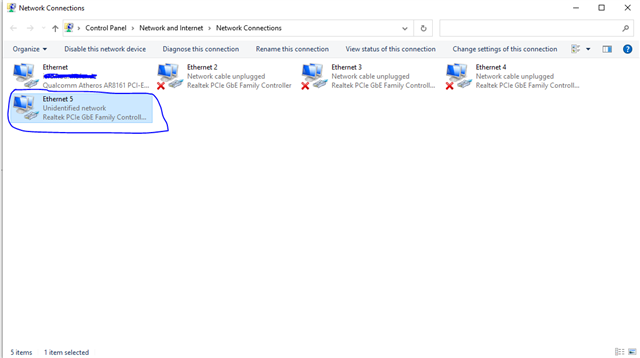
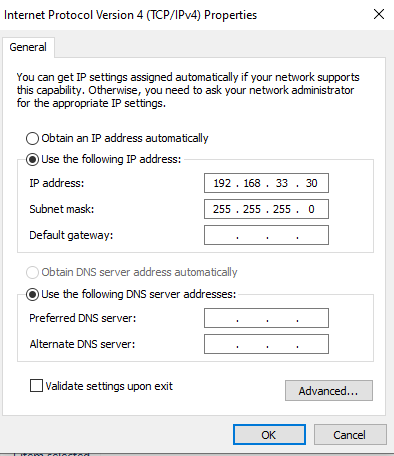
Changed the LAN settings as per DCA1000EVM set up. 

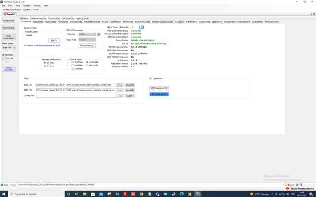
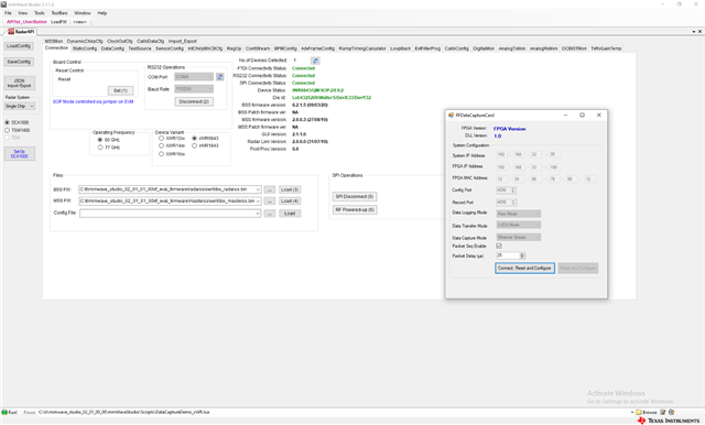
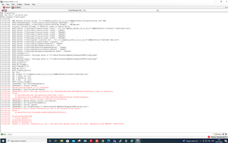
I have opened the mmwave studio Version 2.1.1.0 and got this error! t

Errors:

MATLAB Runtime is not installed.

The type insitializer for 'MatlbaPostProcGui.MatlabPostProcGUIClass' threw an exception

Unable to load DLL 'mclmcrrt8_5_1.dll'

Queries

  1. How to cpature RAW DATA from DCA1000EVM board with ISK for Area scanner lab?  
  2. Is there a step to do before opening the mmwave studio ?
  3. Do i need to change any pins on ISK EVM or DCA1000EVM?  The Areascanner lab is flashed on ISK EVM and checked on UNIFLASH and it is working. 
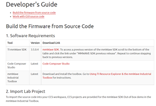
  4. How to link or connect the Code composer Studio + mmwave studio +MATLAB runtime + mmwave SDK ? 
  5. Am i using the right versions for Area scanner Lab? 

Looking for suggestions! Thanks in Advance

Regards,

Shravya 

  • Hello Shravya,

    That error is due to not having specifically version 8.5.1 of MATLAB. You need that specific version of MATLAB for mmWave Studio to work. Below is a link to a more updated and accurate guide for mmWave Sensor Raw Data Capture Using DCA1000 which also has a download link to that specific version.

    0285.mmWave_sensor_raw_data_capture_using_DCA1000_68xx.pptx

    If you want to  ensure you are using the most recent version of Area Scanner, grab it from our more recent TI Resource Explorer Industrial Toolbox page linked here (https://dev.ti.com/tirex/explore/node?a=VLyFKFf__4.11.0&node=AJoMGA2ID9pCPWEKPi16wg__VLyFKFf__4.11.0)

    Last thing is to make sure you set your device to functional mode after flashing the device with Area Scanner binary.

    Best Regards,

    Pedrhom Nafisi

  • Hello!

    I have checked the MATLAB version and I have installed the right 8.5.1 of MATLAB. I have realized that there was two versions of Code composer studio application and I have deleted one of them and I was able to see the mm studio with RADAR API. 

    The versions of the software's are mentioned here: 

    No  

    Software Name  

    Versions 

    1  

    Uniflash   

    Version: 7.1.0.3796  

    2  

    Code Composer Studio  

    Version: 8.3.1.00004  

    3  

    MmWave SDK   

    mmwave_sdk_03_05_00_04-Windows-x86-Install.exe  

    4  

    MMWAVE industrial Toolbox   

       mmwave_industrial_toolbox_4_4_1_

    5  

    MMWave studio  

    Version 2.1.1.0 

    MATLAB Runtime: 8.5.1 

    8.5.1 

    Steps I have performed : 

    • Connected the DCA1000EVM to IWR6843ISK as per the picture.  
    • Connected all the wired connections via Ethernet cable and USB cables. Turned on the Power Supply on the DCA board.  
    • Device manager: Checked the ports  
    • Flash the Areas scanner demo into the ISK using UNI FLASH in flash mode and later in Functional Mode 
    • The ISK is in functional Mode now.  
    • Changed the Settings in the ETHERNET Cable network as below for the highlighted Ethernet network: 

    Device Manager: 

    Control Panel: I have connected the Ethernet Lan Cable to other port and I have changed the IP address. 

    RADAR API:  

    Output:  

    GM: Constructor 

    GM: Fri Jul 22 14:39:24 2022 

    RSTD.Transmit("/Settings") 

    [14:39:24]   

    [14:39:24]  ### Running Startup script: "C:\ti\mmwave_studio_02_01_00_00\mmWaveStudio\Scripts\Startup.lua" ### 

    [14:39:24]  RSTD.SetAndTransmit ("/Settings/Scripter/Display DateTime" , "1") 

    [14:39:24]  RSTD.SetAndTransmit ("/Settings/Scripter/DateTime Format" , "HH:mm:ss") 

    [14:39:24]  Scripter ignored: Attempt to UnBuild() again or before Build. 

    [14:39:24]  RSTD.SetVar ("/Settings/Clients/Client 0/Dll" , "C:\\ti\\mmwave_studio_02_01_00_00\\mmWaveStudio\\Clients\\\\LabClient.dll") 

    [14:39:24]  RSTD.SetVar ("/Settings/Clients/Client 0/Use" , "TRUE") 

    [14:39:24]  RSTD.SetVar ("/Settings/Clients/Client 1/Use" , "FALSE") 

    [14:39:24]  RSTD.SetVar ("/Settings/Clients/Client 2/Use" , "FALSE") 

    [14:39:24]  RSTD.SetVar ("/Settings/Clients/Client 3/Use" , "FALSE") 

    [14:39:24]  RSTD.SetVar ("/Settings/Clients/Client 4/Use" , "FALSE") 

    [14:39:24]  RSTD.SetVar ("/Settings/AL Client/AL Dll" , "C:\\ti\\mmwave_studio_02_01_00_00\\mmWaveStudio\\RunTime\\SAL.dll") 

    [14:39:24]  RSTD.SetVar ("/Settings/Clients/Client 0/GuiDll" , "") 

    [14:39:24]  RSTD.SetVar ("/Settings/AutoUpdate/Enabled" , "TRUE") 

    [14:39:24]  RSTD.SetVar ("/Settings/AutoUpdate/Interval" , "1") 

    [14:39:24]  RSTD.SetVar ("/Settings/Monitors/UpdateDisplay" , "TRUE") 

    [14:39:24]  RSTD.SetVar ("/Settings/Monitors/OneClickStart" , "TRUE") 

    [14:39:24]  RSTD.SetVar ("/Settings/Automation/Automation Mode" , "false") 

    [14:39:24]  RSTD.Transmit("/") 

    [14:39:24]  RSTD.SaveSettings(): Settings saved to "C:\Users\krusche\AppData\Roaming\RSTD\config.xml" 

    [14:39:24]  RSTD.Build() 

    [14:39:24]  RSTD.SaveSettings(): Settings saved to "C:\Users\krusche\AppData\Roaming\RSTD\config.xml" 

    [14:39:24]  RSTD.Transmit("/") 

    [14:39:25]  RSTD.AL_Build() 

    [14:39:25]  RSTD.AL_LoadXml() 

    [14:39:25]  RSTD.Transmit("/") 

    [14:39:25]  RSTD.AL_Init() 

    [14:39:25]  RSTD.Clients_Build() 

    [14:39:25]  GM: Init 

    [14:39:25]  GM: Loaded 'C:\ti\mmwave_studio_02_01_00_00\mmWaveStudio\Clients\\LabClient.dll' 

    [14:39:25]  GM: 1 Guest (s) init 

    [14:39:25]  GM: 1 Module(s) init 

    [14:39:25]  GM: 2 Tab   (s) init 

    [14:39:25]  RSTD.Client_LoadXml() 

    [14:39:25]  [RadarAPI]: ar1.selectRadarMode(0) 

    [14:39:25]  [RadarAPI]: Status: Passed 

    [14:39:25]  Matlab Runtime Engine is installed 

    [14:39:25]  [RadarAPI]: Starting Matlab Engine.. 

    [14:40:00]  [RadarAPI]: Matlab Engine Started! 

    [14:40:02]  [RadarAPI]: ar1.selectCascadeMode(0) 

    [14:40:02]  [RadarAPI]: Status: Passed 

    [14:40:02]  [RadarAPI]: ar1.LoadSettings('C:\Users\krusche\AppData\Roaming\RSTD\ar1gui.ini') 

    [14:40:02]  [RadarAPI]: Error: Index was outside the bounds of the array. 

    [14:40:02]  Trace: 

    [14:40:02]     at AR1xController.ScriptOps.getMatlabPostProcVersion() 

    [14:40:03]  TESTING = false 

    [14:40:03]  RstdNet: Port 2777: Listening.. 

    [14:40:03]   

    [14:40:03]  ***Script completed successfully.*** 

    Tried Another Time: And faced the below

    After connecting the Hardware set up as per picture.  The pins from DCA1000EVM and IWR6843ISK are shown below

    I have opened the mm wave studio and got to see this on OUTPUT shell: 

    OUTPUT After setting the PINS on DCA1000EVM and IWR6843ISK like this:  

    GM: Constructor 

    GM: Fri Jul 22 16:12:14 2022 

    RSTD.Transmit("/Settings") 

    [16:12:15]   

    [16:12:15]  ### Running Startup script: "C:\ti\mmwave_studio_02_01_00_00\mmWaveStudio\Scripts\Startup.lua" ### 

    [16:12:15]  RSTD.SetAndTransmit ("/Settings/Scripter/Display DateTime" , "1") 

    [16:12:15]  RSTD.SetAndTransmit ("/Settings/Scripter/DateTime Format" , "HH:mm:ss") 

    [16:12:15]  Scripter ignored: Attempt to UnBuild() again or before Build. 

    [16:12:15]  RSTD.SetVar ("/Settings/Clients/Client 0/Dll" , "C:\\ti\\mmwave_studio_02_01_00_00\\mmWaveStudio\\Clients\\\\LabClient.dll") 

    [16:12:15]  RSTD.SetVar ("/Settings/Clients/Client 0/Use" , "TRUE") 

    [16:12:15]  RSTD.SetVar ("/Settings/Clients/Client 1/Use" , "FALSE") 

    [16:12:15]  RSTD.SetVar ("/Settings/Clients/Client 2/Use" , "FALSE") 

    [16:12:15]  RSTD.SetVar ("/Settings/Clients/Client 3/Use" , "FALSE") 

    [16:12:15]  RSTD.SetVar ("/Settings/Clients/Client 4/Use" , "FALSE") 

    [16:12:15]  RSTD.SetVar ("/Settings/AL Client/AL Dll" , "C:\\ti\\mmwave_studio_02_01_00_00\\mmWaveStudio\\RunTime\\SAL.dll") 

    [16:12:15]  RSTD.SetVar ("/Settings/Clients/Client 0/GuiDll" , "") 

    [16:12:15]  RSTD.SetVar ("/Settings/AutoUpdate/Enabled" , "TRUE") 

    [16:12:15]  RSTD.SetVar ("/Settings/AutoUpdate/Interval" , "1") 

    [16:12:15]  RSTD.SetVar ("/Settings/Monitors/UpdateDisplay" , "TRUE") 

    [16:12:15]  RSTD.SetVar ("/Settings/Monitors/OneClickStart" , "TRUE") 

    [16:12:15]  RSTD.SetVar ("/Settings/Automation/Automation Mode" , "false") 

    [16:12:15]  RSTD.Transmit("/") 

    [16:12:15]  RSTD.SaveSettings(): Settings saved to "C:\Users\krusche\AppData\Roaming\RSTD\config.xml" 

    [16:12:15]  RSTD.Build() 

    [16:12:15]  RSTD.SaveSettings(): Settings saved to "C:\Users\krusche\AppData\Roaming\RSTD\config.xml" 

    [16:12:15]  RSTD.Transmit("/") 

    [16:12:15]  RSTD.AL_Build() 

    [16:12:15]  RSTD.AL_LoadXml() 

    [16:12:15]  RSTD.Transmit("/") 

    [16:12:15]  RSTD.AL_Init() 

    [16:12:15]  RSTD.Clients_Build() 

    [16:12:15]  GM: Init 

    [16:12:15]  GM: Loaded 'C:\ti\mmwave_studio_02_01_00_00\mmWaveStudio\Clients\\LabClient.dll' 

    [16:12:15]  GM: 1 Guest (s) init 

    [16:12:15]  GM: 1 Module(s) init 

    [16:12:15]  GM: 2 Tab   (s) init 

    [16:12:15]  RSTD.Client_LoadXml() 

    [16:12:15]  [RadarAPI]: ar1.selectRadarMode(0) 

    [16:12:15]  [RadarAPI]: Status: Passed 

    [16:12:15]  Matlab Runtime Engine is installed 

    [16:12:15]  [RadarAPI]: Starting Matlab Engine.. 

    [16:12:18]  [RadarAPI]: Matlab Engine Started! 

    [16:12:20]  [RadarAPI]: ar1.selectCascadeMode(0) 

    [16:12:20]  [RadarAPI]: Status: Passed 

    [16:12:20]  [RadarAPI]: ar1.LoadSettings('C:\Users\krusche\AppData\Roaming\RSTD\ar1gui.ini') 

    [16:12:20]  [RadarAPI]: Error: Index was outside the bounds of the array. 

    [16:12:20]  Trace: 

    [16:12:20]     at AR1xController.ScriptOps.getMatlabPostProcVersion() 

    [16:12:21]  TESTING = false 

    [16:12:21]  RstdNet: Port 2777: Listening.. 

    [16:12:21]   

    [16:12:21]  ***Script completed successfully.*** 

    [16:24:17]  [RadarAPI]: Opening Gpio Control Port() 

    [16:24:17]  [RadarAPI]: Status: Passed 

    [16:24:18]  [RadarAPI]: Opening Board Control Port() 

    [16:24:18]  [RadarAPI]: Status: Passed 

    [16:24:18]  [RadarAPI]: ar1.frequencyBandSelection("60G") 

    [16:24:19]  [RadarAPI]: ar1.FullReset() 

    [16:24:19]  [RadarAPI]: Status: Passed 

    [16:24:19]  [RadarAPI]: ar1.SelectChipVersion("IWR6843") 

    [16:24:19]  [RadarAPI]: Status: Passed 

    [16:24:19]  [RadarAPI]: ar1.deviceVariantSelection("IWR6843") 

    [16:24:19]  [RadarAPI]: Status: Passed 

    [16:24:19]  [RadarAPI]: Closing Board Control Port() 

    [16:24:19]  [RadarAPI]: Status: Passed 

    [16:24:20]  [RadarAPI]: Closing Gpio Control Port() 

    [16:24:20]  [RadarAPI]: Status: Passed 

    [16:24:20]  [RadarAPI]: ar1.SOPControl(2) 

    [16:24:20]  [RadarAPI]: Status: Passed 

    [16:24:21]  [RadarAPI]: ar1.Connect(4,115200,1000) 

    [16:24:23]  [RadarAPI]: Warning: #####Timeout : 100 

    [16:24:23]  [RadarAPI]: Warning: #####Timeout : 100 

    [16:24:23]  [RadarAPI]: Warning: #####Timeout : 100 

    [16:24:23]  [RadarAPI]: Error: Connection failed: Calling_ConnectTarget returned 3 

    [16:24:23]  [RadarAPI]: ar1.Calling_IsConnected() 

    [16:24:23]  [RadarAPI]: ar1.SaveSettings('C:\Users\krusche\AppData\Roaming\RSTD\ar1gui.ini') 

    [16:24:27]  [RadarAPI]: ar1.DownloadBSSFw("C:\\ti\\mmwave_studio_02_01_00_00\\rf_eval_firmware\\radarss\\xwr68xx_radarss.bin") 

    [16:24:27]  [RadarAPI]: Error: Download FW failed with error -1 

    [16:24:29]  [RadarAPI]: ar1.DownloadMSSFw("C:\\ti\\mmwave_studio_02_01_00_00\\rf_eval_firmware\\masterss\\xwr68xx_masterss.bin") 

    [16:24:29]  [RadarAPI]: Error: Download FW failed with error -1 

    [16:25:02]  [RadarAPI]: ar1.PowerOn(0, 1000, 0, 0) 

    [16:25:02]  Status: Failed, Error Type: RESP TIMEOUT 

    [16:25:06]  MSS Power Up async event was not received! 

    Tried another time same procedure and faced the below errors: 

    • MSS Power Up async event was not received!
    • [RadarAPI]: Error: Index was outside the bounds of the array. 
    • Not able to see RS232 Connectivity Status and SPI connectivity Status
    • Facing error when clicking the RF Power-up button Error: RadarAPI: "Readregister" failed with error -2"

     OUTPUT: 

    Queries: 

    • How to make the RS232 and SPI Connectivity Status to connected ?
    • what are the pins to be connected on DCA1000EVM and IWR6843ISK,  How to connect the suitable SOP Mode ?
    • am I missing any steps in this process? 
    • My objective is to RAW Data Capture: I am not able to see the raw captures data.

    I have followed these documents: 

    • DCA1000EVM Quick Start Guide   
    • DCA1000EVM Data Capture Card User's Guide (Rev C) 
    • 1588.DCA1000 Debugging Handbook.pdf 
    • mmWave Sensor Raw Data Capture Using the DCA1000 Board and mmWave Studio Presentation:  


    Looking for suggestions

  • Hello,

    I can confirm this:

    • Your switches on the DCA1000 and ISK are correct
    • You are using the correct radarss.bin and masterss.bin files
    • Ethernet/IP address is correct

    A few suggestions I can provide:

    • Flash the device with Area Scanner's binary file from the newest version of the Industrial toolbox (4.11). You can download it from TIREX by clicking the three vertical buttons when you hover your mouse over "Industrial Toolbox - 4.11.0" https://dev.ti.com/tirex/explore/node?a=VLyFKFf__4.11.0&node=AJoMGA2ID9pCPWEKPi16wg__VLyFKFf__4.11.0
    • Is the COM port accessible? Try using TeraTerm in order to communicate with the device, this will show if your computer can communicate with the ISK or if there is something holding that port hostage. You can follow the first half of this guide for setting up TeraTerm, and then send over the Area Scanner configuration file via copy and paste of the cfg parameters. https://dev.ti.com/tirex/explore/node?a=VLyFKFf__4.11.0&node=ACeLNnq-7-B.6PnmfPHO0Q__VLyFKFf__4.11.0
    • Try turning off your firewall. Unfortunately, in rare instances Windows firewall can actually block proper communication with the board. This is usually the ethernet portion of communication.

    Best Regards,

    Pedrhom Nafisi

  • Hello, 

    Could you tell me why ??

    1. What is the reason that  RS232/SPI  is not connect ? what does this mean ? I would like to get an understanding as well

    2. Why does it mean when I am facing errors like: 

    • MSS Power Up async event was not received!
    • [RadarAPI]: Error: Index was outside the bounds of the array. 

    3. Where Can i find the DCA100EVM and ISK correct switches to refer, could you share the document name? The one I followed is by other forum post. 

    4. Do I need to run any other file? As per the training video I have run only this file in mmstudio. I have run this file: DataCaptureDemo_xWR.lua . 

    Regards

    Shravya 

  • Hi,

    To be clear, there is no reason really to do raw data capture using the Area Scanner lab.

    1. The Area Scanner lab likely does not have the knobs to enable the correct outputs and to interact with mmWave studio properly

    2. The raw data will look the same regardless of what demo you are using, since it is raw data before it has gone through any of the processing done by the lab. 
    3. When you load the MSS FW in one of the steps to work with mmWave studio, it would be overwriting the Area Scanner binary.


    In order to debug further, can you try to manually run through the steps to configure mmWave studio, rather than running the script? I think this may make debugging easier. You can follow these steps by looking at the dca training video which you linked, starting at the 6 minute mark. Go through it step by step, and let me know what the first error you encounter is.

    Best Regards,
    Alec

  • Hello @Alec May

    I have performed the steps mentioned above and still the same error. When I tried connecting the IWR1843BOOST EVM board to mmstudio. The RS232 connectivty seems worked. 

    Could you please confirm what are the correct versions of the Software's and files and drivers needed for capturing Raw data from IWR6843ISK ES 2.0  using DCA1000EVM. I have version ES 2.0 IWR6843ISK standard antenna plug in module.  

    PLEASE MENTION THE CORRECT VERSIONS: 

    • MMWAVE Studio: ?
    • MMWAVE SDK : ?
    • Code composer Studio: ?
    • MMWave Industrial Tool Box:?
    • COM Port Drivers: ?
    • Can you send me the correct BSS FW and MSS FW versions which is compatible for IWR6843ISK ES 2.0  + DCA1000EVM.

    If I could this information, then it will be easy for me to proceed with the Raw Data capture as I have realised that versions of the softwares and files could be one of the issue. 

    Best Regards,

    Shravya 

  • Hello Shravya,

    Best Regards,

    Pedrhom Nafisi

  • Hello, 

    I am able to establish the connection of DCA and ISK and RS232 and SPI connectivity is established. As per the DCA training video, I
     have tried to perform the next steps in which I need to  set up the staticconfig, DataConfig and SensorConfig tab and setup DCA1000 Tab. 

    Errors: Facing errors as DCA1000EVM set up or capturing the data was unsuccessful.  

    All connections are successful and mmstudio is able to detect the version of ISK board. 

    Error: Facing error as "", after clicking the Connect, Reset and Configure tab of dialog box RFDataCaptureCard as per screenshot before. 


    Debugging steps:  

    • Checked the Network Settings and IP Address settings and tested by disconnecting the LAN Cable and tested again with LAN Cable. Ideally the IP address settings are set already for the detected ethernet port from the DCA1000EVM board. 
    • Tested the DCA1000EVM board data capture for chirp data and frame data and post processing utility, faced errors and attached the mm wave studio OUTPUT WINDOW below.  

    OUTPUT:

    MMWave studio OUTPUT:  

    GM: Constructor 

    GM: Thu Jul 28 14:58:29 2022 

    RSTD.Transmit("/Settings") 

    [14:58:30]   

    [14:58:30]  ### Running Startup script: "C:\ti\mmwave_studio_02_01_01_00\mmWaveStudio\Scripts\Startup.lua" ### 

    [14:58:30]  RSTD.SetAndTransmit ("/Settings/Scripter/Display DateTime" , "1") 

    [14:58:30]  RSTD.SetAndTransmit ("/Settings/Scripter/DateTime Format" , "HH:mm:ss") 

    [14:58:30]  Scripter ignored: Attempt to UnBuild() again or before Build. 

    [14:58:30]  RSTD.SetVar ("/Settings/Clients/Client 0/Dll" , "C:\\ti\\mmwave_studio_02_01_01_00\\mmWaveStudio\\Clients\\\\LabClient.dll") 

    [14:58:30]  RSTD.SetVar ("/Settings/Clients/Client 0/Use" , "TRUE") 

    [14:58:30]  RSTD.SetVar ("/Settings/Clients/Client 1/Use" , "FALSE") 

    [14:58:30]  RSTD.SetVar ("/Settings/Clients/Client 2/Use" , "FALSE") 

    [14:58:30]  RSTD.SetVar ("/Settings/Clients/Client 3/Use" , "FALSE") 

    [14:58:30]  RSTD.SetVar ("/Settings/Clients/Client 4/Use" , "FALSE") 

    [14:58:30]  RSTD.SetVar ("/Settings/AL Client/AL Dll" , "C:\\ti\\mmwave_studio_02_01_01_00\\mmWaveStudio\\RunTime\\SAL.dll") 

    [14:58:30]  RSTD.SetVar ("/Settings/Clients/Client 0/GuiDll" , "") 

    [14:58:30]  RSTD.SetVar ("/Settings/AutoUpdate/Enabled" , "TRUE") 

    [14:58:30]  RSTD.SetVar ("/Settings/AutoUpdate/Interval" , "1") 

    [14:58:30]  RSTD.SetVar ("/Settings/Monitors/UpdateDisplay" , "TRUE") 

    [14:58:30]  RSTD.SetVar ("/Settings/Monitors/OneClickStart" , "TRUE") 

    [14:58:30]  RSTD.SetVar ("/Settings/Automation/Automation Mode" , "false") 

    [14:58:30]  RSTD.Transmit("/") 

    [14:58:30]  RSTD.SaveSettings(): Settings saved to "C:\Users\krusche\AppData\Roaming\RSTD\config.xml" 

    [14:58:30]  RSTD.Build() 

    [14:58:30]  RSTD.SaveSettings(): Settings saved to "C:\Users\krusche\AppData\Roaming\RSTD\config.xml" 

    [14:58:30]  RSTD.Transmit("/") 

    [14:58:30]  RSTD.AL_Build() 

    [14:58:30]  RSTD.AL_LoadXml() 

    [14:58:30]  RSTD.Transmit("/") 

    [14:58:30]  RSTD.AL_Init() 

    [14:58:30]  RSTD.Clients_Build() 

    [14:58:30]  GM: Init 

    [14:58:30]  GM: Loaded 'C:\ti\mmwave_studio_02_01_01_00\mmWaveStudio\Clients\\LabClient.dll' 

    [14:58:30]  GM: 1 Guest (s) init 

    [14:58:30]  GM: 1 Module(s) init 

    [14:58:30]  GM: 2 Tab   (s) init 

    [14:58:30]  RSTD.Client_LoadXml() 

    [14:58:30]  [RadarAPI]: ar1.selectRadarMode(0) 

    [14:58:30]  [RadarAPI]: Status: Passed 

    [14:58:30]  Matlab Runtime Engine is installed 

    [14:58:30]  [RadarAPI]: Starting Matlab Engine.. 

    [14:58:35]  [RadarAPI]: Matlab Engine Started! 

    [14:58:37]  [RadarAPI]: ar1.selectCascadeMode(0) 

    [14:58:37]  [RadarAPI]: Status: Passed 

    [14:58:37]  [RadarAPI]: ar1.LoadSettings('C:\Users\krusche\AppData\Roaming\RSTD\ar1gui.ini') 

    [14:58:37]  [RadarAPI]: Error: Index was outside the bounds of the array. 

    [14:58:37]  Trace: 

    [14:58:37]     at AR1xController.ScriptOps.getMatlabPostProcVersion() 

    [14:58:37]  TESTING = false 

    [14:58:37]  RstdNet: Port 2777: Listening.. 

    [14:58:37]   

    [14:58:37]  ***Script completed successfully.*** 

    [14:58:51]  [RadarAPI]: Opening Gpio Control Port() 

    [14:58:51]  [RadarAPI]: Status: Passed 

    [14:58:51]  [RadarAPI]: Opening Board Control Port() 

    [14:58:51]  [RadarAPI]: Status: Passed 

    [14:58:53]  [RadarAPI]: ar1.FullReset() 

    [14:58:53]  [RadarAPI]: Status: Passed 

    [14:58:53]  [RadarAPI]: Closing Board Control Port() 

    [14:58:53]  [RadarAPI]: Status: Passed 

    [14:58:53]  [RadarAPI]: Closing Gpio Control Port() 

    [14:58:53]  [RadarAPI]: Status: Passed 

    [14:58:53]  [RadarAPI]: ar1.SOPControl(2) 

    [14:58:53]  [RadarAPI]: Status: Passed 

    [14:58:56]  [RadarAPI]: ar1.Connect(4,115200,1000) 

    [14:58:57]  [RadarAPI]: ar1.Calling_IsConnected() 

    [14:58:58]  [RadarAPI]: ar1.SelectChipVersion("IWR6843") 

    [14:58:58]  [RadarAPI]: Status: Passed 

    [14:58:58]  [RadarAPI]: ar1.frequencyBandSelection("60G") 

    [14:58:58]  [RadarAPI]: ar1.SelectChipVersion("IWR6843") 

    [14:58:58]  [RadarAPI]: Status: Passed 

    [14:58:58]  Device Status : IWR6843/QM/SOP:2/ES:2 

    [14:58:58]  [RadarAPI]: ar1.SaveSettings('C:\Users\krusche\AppData\Roaming\RSTD\ar1gui.ini') 

    [14:59:02]  [RadarAPI]: ar1.DownloadBSSFw("C:\\ti\\mmwave_studio_02_01_01_00\\rf_eval_firmware\\radarss\\xwr68xx_radarss.bin") 

    [14:59:03]  [RadarAPI]: Downloading BSS ROM RPRC Binary.. 

    [14:59:50]  [RadarAPI]: ar1.GetBSSFwVersion() 

    [14:59:50]  [RadarAPI]: BSSFwVersion:(06.02.01.05 (09/03/20)) 

    [15:00:41]  [RadarAPI]: ar1.DownloadMSSFw("C:\\ti\\mmwave_studio_02_01_01_00\\rf_eval_firmware\\masterss\\xwr68xx_masterss.bin") 

    [15:00:41]  [RadarAPI]: Downloading MSS RPRC Binary.. 

    [15:01:00]  [RadarAPI]: ar1.GetMSSFwVersion() 

    [15:01:00]  [RadarAPI]: MSSFwVersion:(02.00.00.03 (27/08/19)) 

    [15:01:04]  [RadarAPI]: ar1.PowerOn(0, 1000, 0, 0) 

    [15:01:04]  [RadarAPI]: Status: Passed 

    [15:01:04]  MSS power up done async event received! 

    [15:01:07]  [RadarAPI]: ar1.SelectChipVersion("IWR6843") 

    [15:01:07]  [RadarAPI]: Status: Passed 

    [15:01:07]  [RadarAPI]: ar1.SelectChipVersion("IWR6843") 

    [15:01:07]  [RadarAPI]: Status: Passed 

    [15:01:07]  Device Status : IWR6843/QM/SOP:2/ES:2 

    [15:01:07]  [RadarAPI]: ar1.RfEnable() 

    [15:01:07]  BSS power up done async event received! 

    [15:01:07]  [RadarAPI]: Status: Passed 

    [15:01:07]  [RadarAPI]: ar1.GetMSSFwVersion() 

    [15:01:07]  [RadarAPI]: MSSFwVersion:(02.00.00.03 (27/08/19)) 

    [15:01:08]  [RadarAPI]: ar1.GetBSSFwVersion() 

    [15:01:08]  [RadarAPI]: BSSFwVersion:(06.02.01.05 (09/03/20)) 

    [15:01:18]  [RadarAPI]: ar1.ChanNAdcConfig(1, 1, 1, 1, 1, 1, 1, 2, 1, 0) 

    [15:01:18]  [RadarAPI]: Status: Passed 

    [15:01:21]  [RadarAPI]: ar1.LPModConfig(0, 0) 

    [15:01:21]  [RadarAPI]: Status: Passed 

    [15:01:22]  [RadarAPI]: ar1.RfInit() 

    [15:01:23]  RF Init async event received! 

    [15:01:23]  [RadarAPI]: Time stamp, Temperture: 15459,44; APLL Status, Update: 1, 0; SynthVCO1 Status, Update: 1, 1; SynthVCO2 Status, Update: 1, 1; LODist Status, Update: 1, 1; RxADCDC Status, Update: 1, 1; HPFcutoff Status, Update: 1, 1; LPFcutoff Status, Update: 1, 1; PeakDetector Status, Update: 1, 1; TxPower Status, Update: 1, 1; RxGain Status, Update: 1, 1; TxPhase Status, Update: 1, 1; RxIQMM Status, Update: 1, 1;  

    [15:01:23]  [RadarAPI]: Status: Passed 

    [15:01:29]  [RadarAPI]: ar1.DataPathConfig(513, 1216644097, 0) 

    [15:01:29]  [RadarAPI]: Status: Passed 

    [15:01:31]  [RadarAPI]: ar1.LvdsClkConfig(1, 1) 

    [15:01:31]  [RadarAPI]: Status: Passed 

    [15:01:33]  [RadarAPI]: ar1.LVDSLaneConfig(0, 1, 1, 0, 0, 1, 0, 0) 

    [15:01:33]  [RadarAPI]: Status: Passed 

    [15:01:45]  [RadarAPI]: ar1.ProfileConfig(0, 60, 100, 6, 60, 0, 0, 0, 0, 0, 0, 29,982, 0, 256, 10000, 0, 0, 30) 

    [15:01:45]  [RadarAPI]: Status: Passed 

    [15:02:49]  [RadarAPI]: ar1.ChirpConfig(0, 0, 0, 0, 0, 0, 0, 1, 0, 0) 

    [15:02:49]  [RadarAPI]: Status: Passed 

    [15:02:50]  Test Source Already Disabled...!!! 

    [15:02:50]  [RadarAPI]: ar1.DisableTestSource(0) 

    [15:02:50]  [RadarAPI]: Status: Passed 

    [15:02:50]  [RadarAPI]: ar1.FrameConfig(0, 0, 8, 128, 40, 0, 0, 1) 

    [15:02:50]  [RadarAPI]: Status: Passed 

    [15:04:10]  [RadarAPI]: ar1.GetCaptureCardDllVersion() 

    [15:04:10]  [RadarAPI]: Sending dll_version command to DCA1000 

    [15:04:10]  [RadarAPI]:  

    [15:04:10]  DLL Version : 1.0 

    [15:04:10]  [RadarAPI]: ar1.SelectCaptureDevice("DCA1000") 

    [15:04:10]  [RadarAPI]: Status: Passed 

    [15:04:15]  [RadarAPI]: ar1.CaptureCardConfig_EthInit("192.168.33.30", "192.168.33.180", "12:34:56:78:90:12", 4096, 4098) 

    [15:04:15]  [RadarAPI]: ar1.CaptureCardConfig_Mode(1, 2, 1, 2, 3, 30) 

    [15:04:15]  [RadarAPI]: ar1.CaptureCardConfig_PacketDelay(25) 

    [15:04:15]  [RadarAPI]: Sending fpga command to DCA1000 

    [15:04:25]  [RadarAPI]:  

    [15:04:25]  FPGA Configuration :  

    [15:04:25]  Timeout Error! System disconnected 

    [15:04:25]  [RadarAPI]: Sending record command to DCA1000 

    [15:04:36]  [RadarAPI]:  

    [15:04:36]  Configure Record :  

    [15:04:36]  Timeout Error! System disconnected 

    [15:04:36]  [RadarAPI]: ar1.GetCaptureCardFPGAVersion() 

    [15:04:36]  [RadarAPI]: Sending fpga_version command to DCA1000 

    [15:04:46]  [RadarAPI]:  

    [15:04:46]   

    [15:04:46]  Unable to read FPGA Version. [error -5] 

    [15:04:46]   

    [15:11:01]  [RadarAPI]: ar1.CaptureCardConfig_EthInit("192.168.33.30", "192.168.33.180", "12:34:56:78:90:12", 4096, 4098) 

    [15:11:01]  [RadarAPI]: ar1.CaptureCardConfig_Mode(1, 2, 1, 2, 3, 30) 

    [15:11:01]  [RadarAPI]: ar1.CaptureCardConfig_PacketDelay(25) 

    [15:11:01]  [RadarAPI]: Sending fpga command to DCA1000 

    [15:11:11]  [RadarAPI]:  

    [15:11:11]  FPGA Configuration :  

    [15:11:11]  Timeout Error! System disconnected 

    [15:11:11]  [RadarAPI]: Sending record command to DCA1000 

    [15:11:21]  [RadarAPI]:  

    [15:11:21]  Configure Record :  

    [15:11:21]  Timeout Error! System disconnected 

    [15:11:21]  [RadarAPI]: ar1.GetCaptureCardFPGAVersion() 

    [15:11:21]  [RadarAPI]: Sending fpga_version command to DCA1000 

    [15:11:31]  [RadarAPI]:  

    [15:11:31]   

    [15:11:31]  Unable to read FPGA Version. [error -5] 

    [15:11:31]   

    [15:11:48]  [RadarAPI]: ar1.CaptureCardConfig_StartRecord("C:\\ti\\mmwave_studio_02_01_01_00\\mmWaveStudio\\PostProc\\adc_data.bin", 1) 

    [15:11:48]  [RadarAPI]: Sending start_record command to DCA1000 

    [15:11:49]  [RadarAPI]: ar1.StartFrame() 

    [15:11:49]  [RadarAPI]: Status: Passed 

    [15:11:49]  Frame start async event received! 

    [15:11:50]  Frame End async event received! 

    [15:11:50]  [RadarAPI]: Frame Ended 

    [15:11:58]  [RadarAPI]:  

    [15:11:58]  [RadarAPI]:  

    [15:11:58]  Start Record :  

    [15:11:58]  Timeout Error! System disconnected 

    [15:11:58]  [RadarAPI]: ar1.StartMatlabPostProc("C:\\ti\\mmwave_studio_02_01_01_00\\mmWaveStudio\\PostProc\\adc_data.bin") 

    [15:11:58]  [RadarAPI]: No of files Captured: 0, Total no of frames for each device : 8 

    [15:11:58]  Error : The number of files captured is zero! 

    [15:11:58]  [RadarAPI]: ar1.StopFrame() 

    [15:11:58]  Status: Failed, Error Type: FRAME ARE ALREADY STOPPED WHEN THE FRAME_STOP COMMAND WAS ISSUED 

    [15:12:03]  [RadarAPI]: ar1.StopFrame() 

    [15:12:03]  Status: Failed, Error Type: FRAME ARE ALREADY STOPPED WHEN THE FRAME_STOP COMMAND WAS ISSUED 

    [15:12:05]  [RadarAPI]: ar1.StartMatlabPostProc("C:\\ti\\mmwave_studio_02_01_01_00\\mmWaveStudio\\PostProc\\adc_data.bin") 

    [15:12:05]  [RadarAPI]: No of files Captured: 0, Total no of frames for each device : 8 

    [15:12:05]  Error : The number of files captured is zero! 

    [15:13:46]  [RadarAPI]: ar1.CaptureCardConfig_EthInit("192.168.33.30", "192.168.33.180", "12:34:56:78:90:12", 4096, 4098) 

    [15:13:46]  [RadarAPI]: ar1.CaptureCardConfig_Mode(1, 2, 1, 2, 3, 30) 

    [15:13:46]  [RadarAPI]: ar1.CaptureCardConfig_PacketDelay(25) 

    [15:13:46]  [RadarAPI]: Sending fpga command to DCA1000 

    [15:13:56]  [RadarAPI]:  

    [15:13:56]  FPGA Configuration :  

    [15:13:56]  Timeout Error! System disconnected 

    [15:13:56]  [RadarAPI]: Sending record command to DCA1000 

    [15:14:06]  [RadarAPI]:  

    [15:14:06]  Configure Record :  

    [15:14:06]  Timeout Error! System disconnected 

    [15:14:06]  [RadarAPI]: ar1.GetCaptureCardFPGAVersion() 

    [15:14:06]  [RadarAPI]: Sending fpga_version command to DCA1000 

    [15:14:16]  [RadarAPI]:  

    [15:14:16]   

    [15:14:16]  Unable to read FPGA Version. [error -5] 

    [15:14:16]   

    [15:14:41]  [RadarAPI]: ar1.CaptureCardConfig_StartRecord("C:\\ti\\mmwave_studio_02_01_01_00\\mmWaveStudio\\PostProc\\adc_data.bin", 1) 

    [15:14:41]  [RadarAPI]: Sending start_record command to DCA1000 

    [15:14:47]  [RadarAPI]: ar1.StartFrame() 

    [15:14:47]  [RadarAPI]: Status: Passed 

    [15:14:47]  Frame start async event received! 

    [15:14:47]  Frame End async event received! 

    [15:14:47]  [RadarAPI]: Frame Ended 

    [15:14:51]  [RadarAPI]:  

    [15:14:51]  [RadarAPI]:  

    [15:14:51]  Start Record :  

    [15:14:51]  Timeout Error! System disconnected 

    [15:15:05]  [RadarAPI]: ar1.StartMatlabPostProc("C:\\ti\\mmwave_studio_02_01_01_00\\mmWaveStudio\\PostProc\\adc_data.bin") 

    [15:15:05]  [RadarAPI]: No of files Captured: 0, Total no of frames for each device : 8 

    [15:15:05]  Error : The number of files captured is zero! 

    [15:15:20]  [RadarAPI]: ar1.CaptureCardConfig_EthInit("192.168.33.30", "192.168.33.180", "12:34:56:78:90:12", 4096, 4098) 

    [15:15:20]  [RadarAPI]: ar1.CaptureCardConfig_Mode(1, 2, 1, 2, 3, 30) 

    [15:15:20]  [RadarAPI]: ar1.CaptureCardConfig_PacketDelay(25) 

    [15:15:20]  [RadarAPI]: Sending fpga command to DCA1000 

    [15:15:30]  [RadarAPI]:  

    [15:15:30]  FPGA Configuration :  

    [15:15:30]  Timeout Error! System disconnected 

    [15:15:30]  [RadarAPI]: Sending record command to DCA1000 

    [15:15:40]  [RadarAPI]:  

    [15:15:40]  Configure Record :  

    [15:15:40]  Timeout Error! System disconnected 

    [15:15:40]  [RadarAPI]: ar1.GetCaptureCardFPGAVersion() 

    [15:15:40]  [RadarAPI]: Sending fpga_version command to DCA1000 

    [15:15:50]  [RadarAPI]:  

    [15:15:50]   

    [15:15:50]  Unable to read FPGA Version. [error -5] 

    [15:15:50]   

    [15:16:24]  [RadarAPI]: ar1.CaptureCardConfig_StartRecord("C:\\ti\\mmwave_studio_02_01_01_00\\mmWaveStudio\\PostProc\\adc_data.bin", 1) 

    [15:16:24]  [RadarAPI]: Sending start_record command to DCA1000 

    [15:16:34]  [RadarAPI]:  

    [15:16:34]  Start Record :  

    [15:16:34]  Timeout Error! System disconnected 

    [15:16:53]  [RadarAPI]: ar1.StartFrame() 

    [15:16:53]  [RadarAPI]: Status: Passed 

    [15:16:54]  Frame start async event received! 

    [15:16:54]  [RadarAPI]: Frame Ended 

    [15:16:54]  Frame End async event received! 

    [15:17:01]  [RadarAPI]: ar1.StartMatlabPostProc("C:\\ti\\mmwave_studio_02_01_01_00\\mmWaveStudio\\PostProc\\adc_data.bin") 

    [15:17:01]  [RadarAPI]: No of files Captured: 0, Total no of frames for each device : 8 

    [15:17:01]  Error : The number of files captured is zero! 

    [15:17:15]  [RadarAPI]: ar1.StartMatlabPostProc("C:\\ti\\mmwave_studio_02_01_01_00\\mmWaveStudio\\PostProc\\adc_data.bin") 

    [15:17:15]  [RadarAPI]: No of files Captured: 0, Total no of frames for each device : 8 

    [15:17:15]  Error : The number of files captured is zero! 

    QUERIES: 

    QUERIES: 

    • I think the issue could be at LAN/ETHERNET settings, could you please tell me the correct way of connecting  and set up of IP Address settings. 
    • I have LAN connection connected from my office and the DCA1000EVM board ethernet cable is connected to another Ethernet port and that detected network settings are changed as per DCA1000EVM training video to mentioned IP address. 

    I tried both ways: Can you please tell me which way is the right way?

    1. I have connected the LAN cable from office and tried to connect the DCA Ethernet port cable on another slot and the IP address of Ethernet cable network of DCA1000EVM is changed and attached the screenshot above. 
    2. I have removed the LAN cable from office and tried to connect the DCA Ethernet port cable on another slot and the IP address of Ethernet cable network of DCA1000EVM is changed and attached the screenshot above. 

    Important Query: 

    I want to capture data from Area Scanner Lab deployed on DCA1000EVM board + ISK board, what is the process for this? As of now, I have deployed DataDemocapture firmware on mmstudio. 

    Is it possible to establish the Area scanner lab application on DCA and ISK and read the data and capture data from Area scanner lab project? 

    Looking for your reply, 

    Best Regards,

    Shravya 

  • Hello Shravya,

    If you want to use FPGA on the device, you have to make sure you are using the Lattice tool to reprogram the FPGA. Your error of "Unable to read FPGA Version. [error -5]" means it must be re-programmed. You can find instructions on using the tool on the DCA1000 User Guide here: https://www.ti.com/lit/ug/spruij4a/spruij4a.pdf?ts=1659377095259.

    As Alec May said prior, DCA1000EVM + ISK + mmWaveStudio is for raw data only and to reiterate:

    1. The Area Scanner lab likely does not have the knobs to enable the correct outputs and to interact with mmWave studio properly

    2. The raw data will look the same regardless of what demo you are using, since it is raw data before it has gone through any of the processing done by the lab. 

    The correct way to setup the Ethernet data transfer is using the settings you have in your screenshot with IP Address 192.168.33.30 (which is correct), with one side of the cord connected to the DCA1000 and the other directly into your computer.

    Best Regards,

    Pedrhom Nafisi

  • Hello, 

    Could you tell me, how can I evaluate data from Area Scanner Lab. I want to implement the Area Scanner Lab and Analyse the output data in detecting the static and dynamic objects. 

    If its not possible with mm studio, how could I get the Area Scanner Lab implemented and evaluated further? Could you please explain. 

    To explain my project Goal: I want to test the Area Scanner lab demo field in Industrial Space and track the static and dynamic objects by testing the demo field in different scenarios by changing the parameters like distance between sensor and humans, same with Angles and Velocity. I want to analyse the Range,Angle, Velocity data values from my tests. 

    Could you please explain what hardware/software to do this? Is there a different approach to achieve my project goal. 

    Best Regards,

    Shravya 

  • Hi Shravya,

    To be clear, the DCA1000EVM and mmWaveStudio are primarily intended for Raw ADC Data capture, which is typically only necessary if you want to do your own algorithm development from the ground-up. If your goal is to just evaluate the Area Scanner lab, is there any reason why you are not following the steps in the Area Scanner User Guide, and testing the demo with the GUI which is included with it? 

    Best Regards,
    Alec

  • Hello Alec, 

    This is something I am not clear as I thought working with DCA1000EVM + ISK by deploying Area Scanner Lab in ISK will work.

    I have followed the Area Scanner User Guide and I have set the Uniflash in Flash mode and Run the lab and Opened the Visualizer to see the static and dynamic object points by referring this Link: https://dev.ti.com/tirex/explore/content/mmwave_industrial_toolbox_4_10_1/labs/Area_Scanner/docs/area_scanner_users_guide.html#work-with-gui-source-code. In this Visualizer, I am not sure how I can extract the detected results and use the data for testing. I got to see the below output in the command prompt interface when I am trying to open the visualizer.exe file. 

    COM8 opened.
    Opening as_demo_uart_stream.txt. Ready to log data.
    Opening configuration file
    Parsing configuration file...
    COM7 opened.
    COM8 opened.
    Sending cfg file to device...
    sensorStop
    flushCfg
    Done
    dfeDataOutputMode 1
    Done
    channelCfg 15 7 0
    Done
    adcCfg 2 1
    Done
    adcbufCfg -1 0 1 1 1
    Done
    profileCfg 0 60.5 100 25 69 0 0 50 1 256 6000 0 0 30
    Done
    chirpCfg 0 0 0 0 0 0 0 1
    Done
    chirpCfg 1 1 0 0 0 0 0 4
    Done
    chirpCfg 2 2 0 0 0 0 0 2
    Done
    frameCfg 0 2 32 0 100 1 0
    Done
    lowPower 0 0
    Done
    guiMonitor -1 1 0 0 0 0 0
    Done
    cfarCfg -1 0 2 8 4 3 0 20 0
    Done
    cfarCfg -1 1 0 4 2 3 1 15 0
    Done
    multiObjBeamForming -1 1 0.5
    Done
    clutterRemoval -1 1
    Done
    calibDcRangeSig -1 0 -5 8 256
    Done
    extendedMaxVelocity -1 0
    Done
    bpmCfg -1 0 0 1
    Done
    lvdsStreamCfg -1 0 0 0
    Done
    compRangeBiasAndRxChanPhase 0.0 1 0 1 0 1 0 1 0 1 0 1 0 1 0 1 0 1 0 1 0 1 0 1 0
    Done
    measureRangeBiasAndRxChanPhase 0 1.5 0.2
    Done
    CQRxSatMonitor 0 3 15 125 0
    Done
    CQSigImgMonitor 0 115 6
    Done
    analogMonitor 0 0
    Done
    aoaFovCfg -1 -90 90 -90 90
    Done
    cfarFovCfg -1 0 0 11.11
    Done
    cfarFovCfg -1 1 -2.04 2.04
    Done
    staticBoundaryBox -8 8 0 8 -1 2
    Done
    boundaryBox -8 8 0 8 -1 2
    Done
    gatingParam 4 2 2 2 10
    Done
    stateParam 20 10 10 50 1
    Done
    allocationParam 200 155 0.5 10 2 2
    Done
    maxAcceleration 0.1 0.1 0.1
    Done
    trackingCfg 1 2 250 20 20 260 100 90
    Done
    heatmapGenCfg -1 1  0 6 50 60.0 3.0 10
    Done
    staticDetectionCfg -1 0 -50.0 +50.0 -20.0 20.0 0.7 6.0 0.2 4 20.0
    Done
    sensorStart
    Issue with Frame 25. Skipping. Expected packet length: 320; Actual length: 309.
    Issue with Frame 496. Skipping. Expected packet length: 832; Actual length: 547.
    • As I explained my Goal, I want to test the area scanner with 10 -15 test scenarios and use the resulted data for analyzing and evaluation. How to extract the data with Area Scanner Lab. Can you please tell me this? 
    • I want to identify the Range,Velocity, Distance, Static and Dynamic objects, Number of Humans detected and Trigger time and Reaction time of the Sensor in the Area Scanner Lab, Please suggest me the write approach to do this? 
    • Why we cannot work with Area Scanner on DCA1000EVM withhin mmwave studio? Can you please provide relevant reason for this ? That would be helpful in justifying my work approach. 

    Best Regards,

    Shravya 

  • Hi,

    So I will answer your last question first. When you are streaming raw data via the DCA1000, you are basically directly transmitting the data which is collected by the ADC's and skipping any processing that would normally be done on the MCU and DSP which are built into the IWR6843. When we talk about a lab/demo (ie Area Scanner in this case), this is really just a Software image which is ran on the MCU and DSP which captures the data, runs digital signal processing, and outputs some form of processed data (such as a point cloud). Since you are skipping all this processing when doing Raw Data capture, it kind of takes the identity away from the lab, since the raw data will look the same regardless of which demo is on the device.

    Since the demo/lab doesn't affect the raw data, many of our labs do not even have the knobs to directly transmit raw data via the LVDS interface to the DCA1000, which is why one of the steps in mmwave studio is to load an MSS image (for the ARM MCU) which would be overwriting any demo which is loaded (such as Area Scanner). This MSS image has all the knobs built in to handle this raw data transfer, which is why it's used.

    Now, moving on to your questions about how to evaluate the Area Scanner Demo for your use case. This kind of depends on how you want to handle it, so I will give two potential options which I can see. These are not necessarily the only options, but the two most simple ones.

    1.  You run the visualizer included with Area Scanner, and use a screen capture software to record the visualizer, and make a recording for each of your use cases. You then watch back the footage, and analyze visually whether it detected all objects to your standards.
    2. Do not run the visualizer, and simply capture the UART output stream via a serial interface. For example, you could use the logging function in teraterm to capture a full binary log of the data stream for each use case. You would then need to build a parsing algorithm (or copy the one from the Area Scanner visualizer) in order to parse the UART data capture, and display the relevant information that you are looking for in order to evaluate whether it meets your standards. The Area Scanner User guide also has a full section on the format of the UART output data which you could refer to determine what information is relevant to your evaluation.

    Best Regards,
    Alec

  • Hello Alec, Thank you for the brief reply explaining on DCA1000EVM and Area scanner Lab. I have understood well now that Area scanner demo cannot be deployed on DCA1000EVM as it overwrites the process. 

    Coming to Area Scanner Lab itself: 

    I am looking to get the point could data and the output generated by Area Scanner Data sets

    Like These: 

    • Headers 
    • Type Length Values (TLVs) 
    • Detected Object (Dynamic Points) 
    • Detected Object (Dynamic Points) Side Info 
    • Static Detected Object (Static Points) 
    • Static Detected Object (Static Points) Side Info 
    • Tracked Object List 
    • Point to Track Associations  

    As I explained my Test case, that I want to place this Radar Sensor deployed with Area Scanner demo in different scenarios and then detect and track the data. I am looking for data where I can compare these Radar Sensor data results with other reference sensor, this is why I am looking for values like Static, Dynamic coordinates and also parameters like Frequency, Range, Velocity, Angle of the detected Objects and Humans. 

    What I tried apart from Option 1 are:: I have only got the visualizer GUI here not any data to use them further analysis

    What I tried apart from Option 2 are: 

    • I havent found any relevant link but tried to follow the same link and tried to steps under "DEVELOPER'S GUIDE to Build the Firmware from source code"
    • Here are the steps I have followed: 
      • Import Area Scanner Lab into CCS Workspace : Successfully Done 
      • Build the Area Scanner Lab : Successfully Done 
      • Execute the Compiled Lab in Deployment mode :
        • I was unable to understand and execute the complied lab.
        • Do I need to FLASH the Area scanner lab demo in this step?
        • Where Can i get the option to execute the  compiled Lab ?
      • Execute the Compiled Lab in Debug mode : Didn't Perform this step and I was Struck at above steps
      • Work with GUI source code : Didn't Perform this step and I was Struck at above steps
    • Could you please add any manual or relevant support for my queries. Thank you and Have a nice day! 

    Best Regards,

    Shravya 

  • Shravya,

    Since we have deviated so far from the orginal topic of this thread, would you mind opening a new thread? This will help to ensure that other members of the forum are able to easily find topics and issues related to their own. Once you open that thread, we can continue the discussion there.

    Best Regards,
    Alec

  • Hello Alec, 

    Thank for the suggestion. I have added new post and here is the link: https://e2e.ti.com/support/sensors-group/sensors/f/sensors-forum/1125761/iwr6843isk-iwr6843isk-looking-for-area-scanner-demo-output-results-working-with-gui-source-code 

    Could you please provide relevant support on my new post as well. 

    Thank you, 

    Shravya