This thread has been locked.

If you have a related question, please click the "Ask a related question" button in the top right corner. The newly created question will be automatically linked to this question.

AWR1843: no plots shown in mmWave Demo Visualizer

Part Number: AWR1843
Other Parts Discussed in Thread: UNIFLASH, , , TMS320C6748


Hi teams,
    Greetings for the Day!

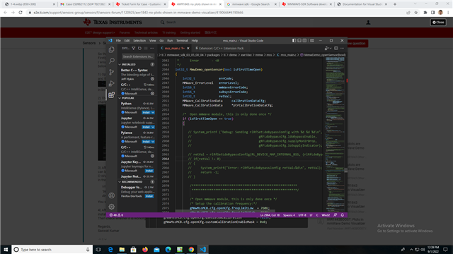
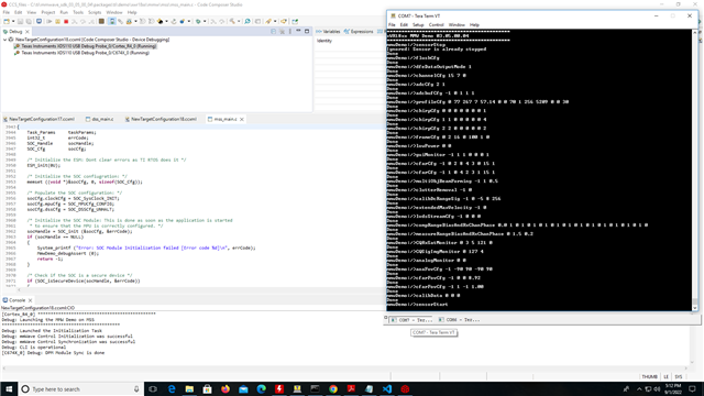
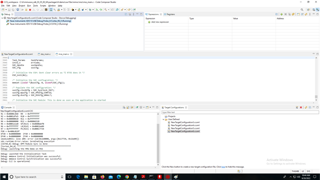
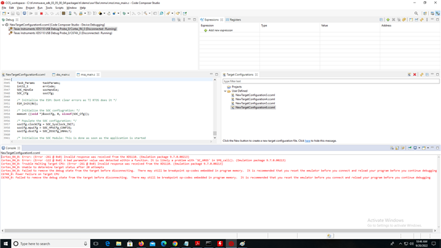
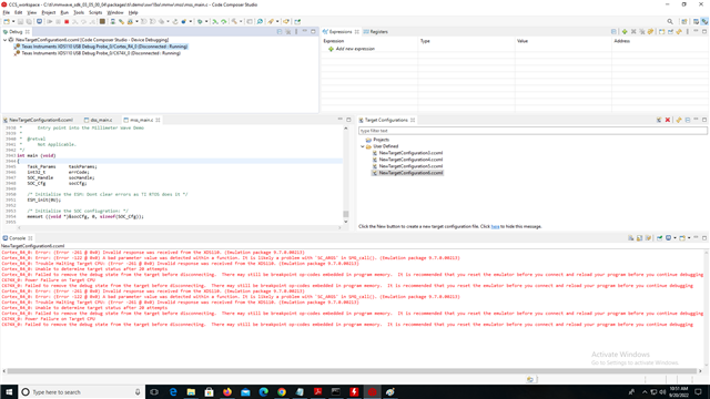
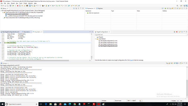
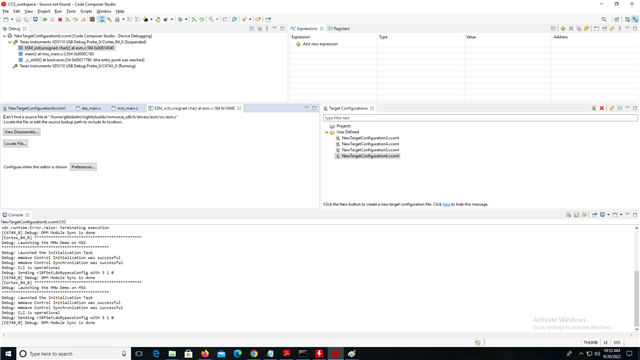
    Since the suggestion in thread 1092373 can not resolved the issue, the customer still request to further help for his issue .
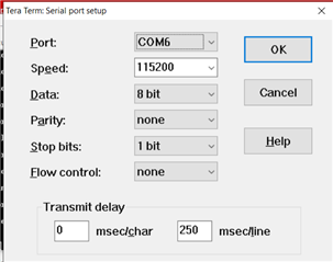
   He checked the COM port available and followed the all suggestions in thread 1092373,but they do not work now.
    There are recent response from the customer. Could you kindly suggest anything others to solve the issue .

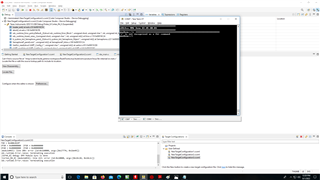
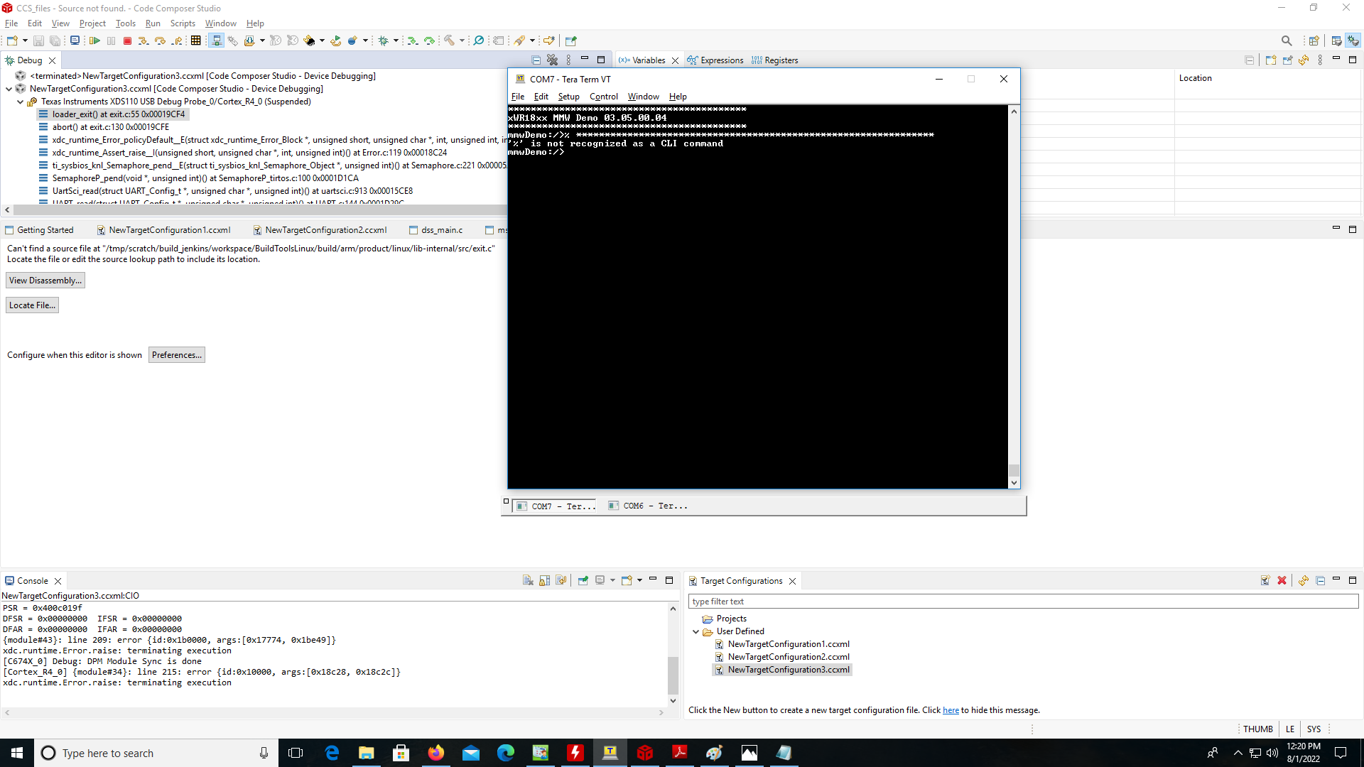
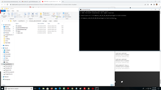
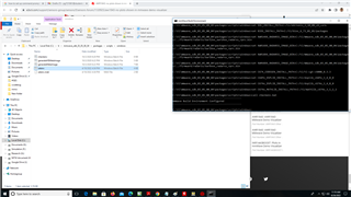
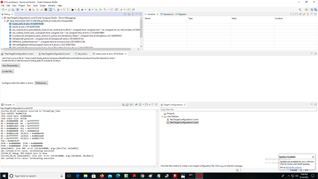
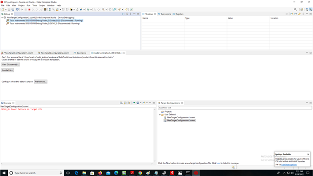
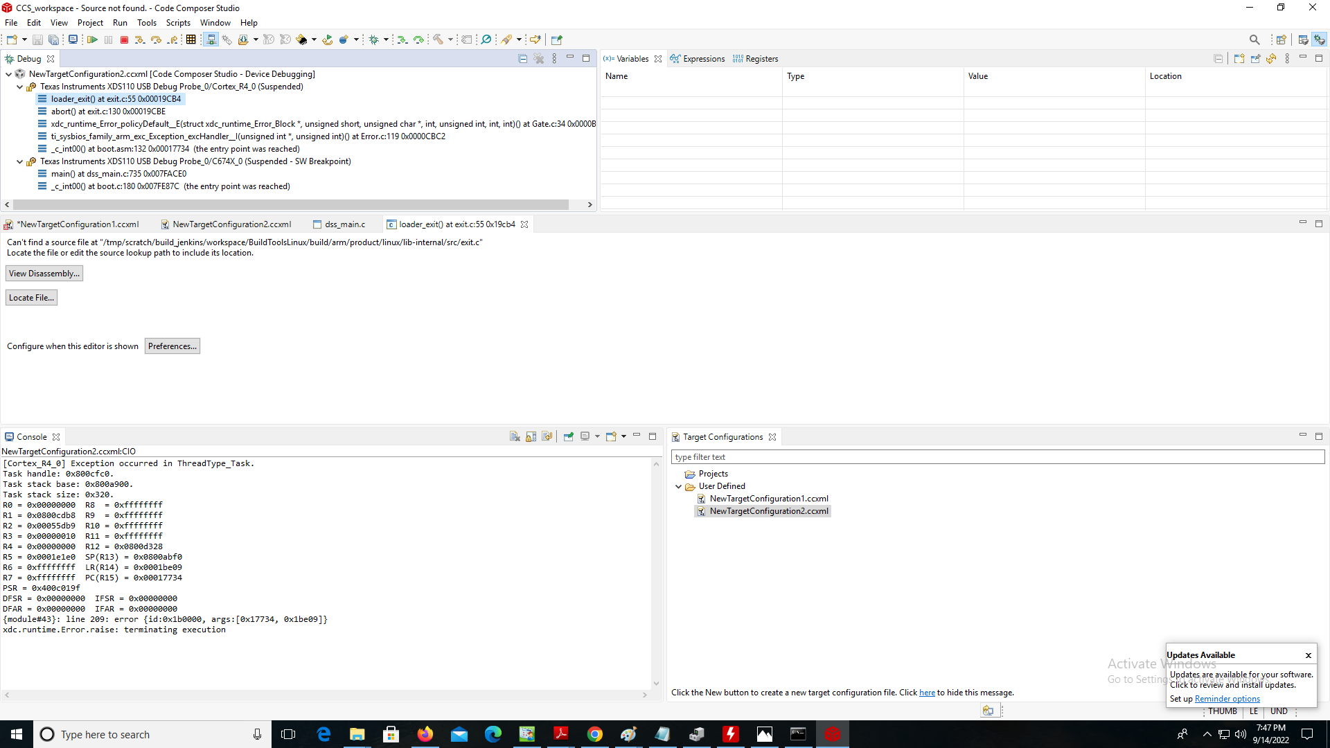
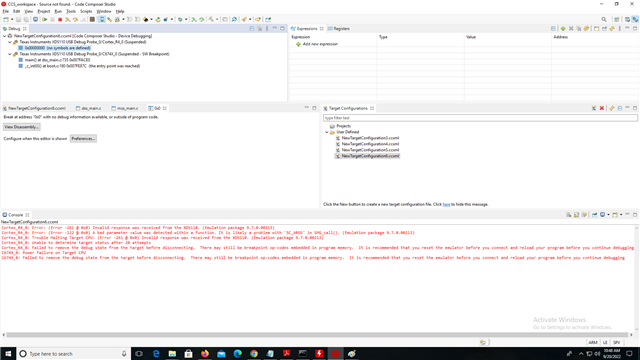
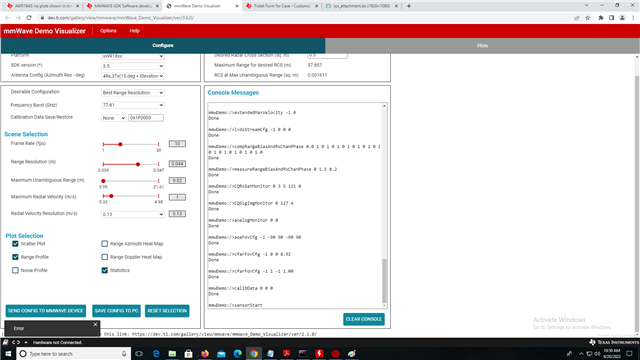
   " I have tested the device with other USB cable. It is still not giving the output. So there is nothing wrong with the cable.
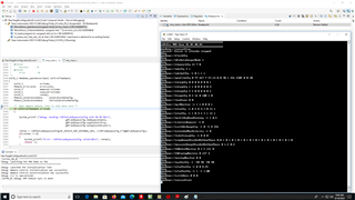
   So I think it is the mmWave SDK software that is malfunctioning. Because the SDK app is unable to get the output from EVM."

     Because the thread 1092373 has been closed for time out  of no further response, I create  this new thread.  I repost the issue again:

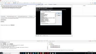
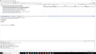
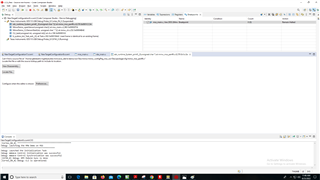
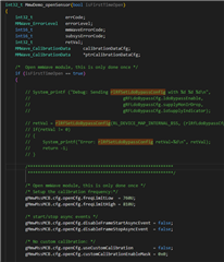
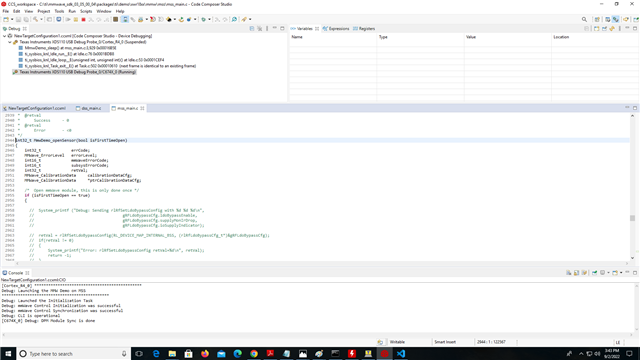
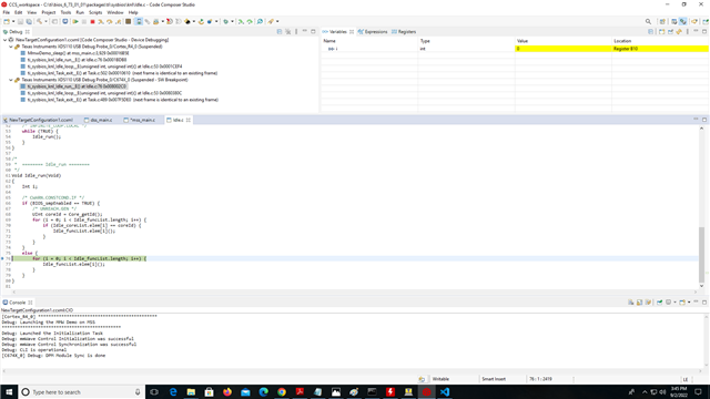
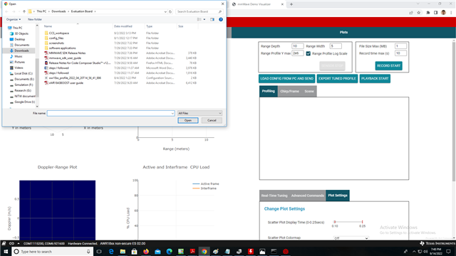
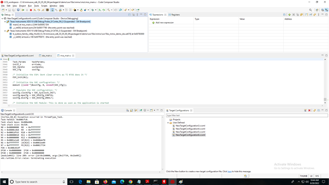
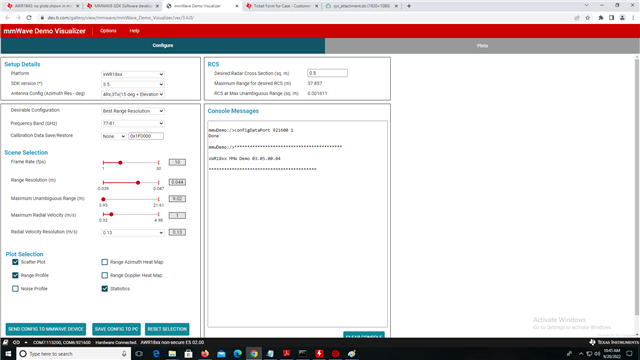
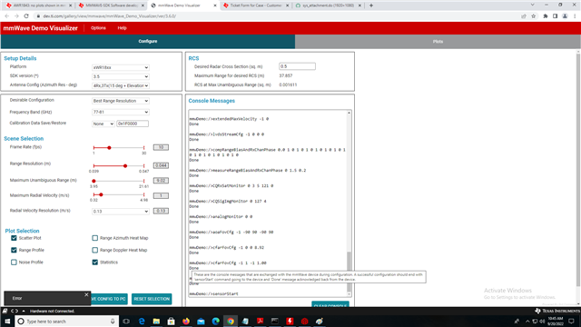
    "  After flashing the device, Do we have to power off the device, to change the SOP jumpers to functional mode, then power up again. (or) We can directly change the SOP jumpers to functional mode after flashing is     successful with the power cable ON.
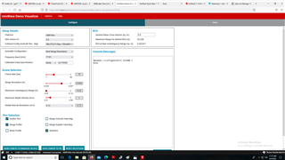
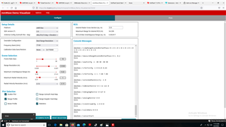
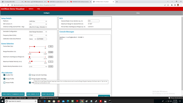
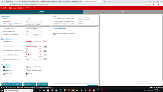
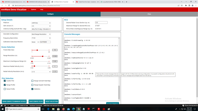
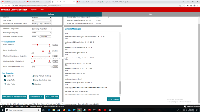
2. The SENSOR STOP button in the 'Plot' tab is not active even after pressing 'SEND CONFIG TO MMWAVE DEVICE' in 'Config' tab. What to do?
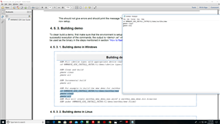
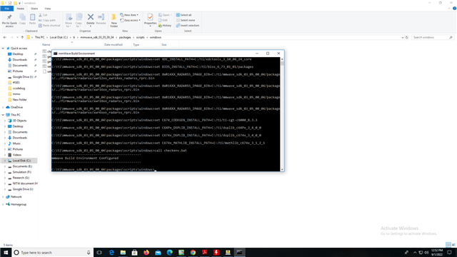
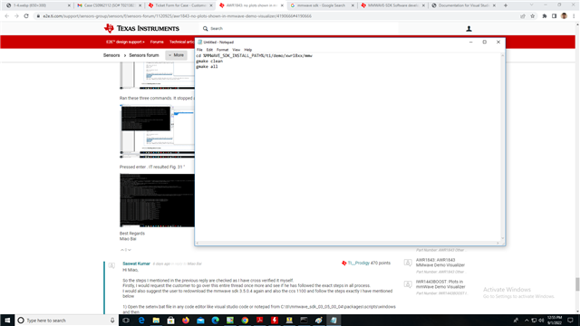
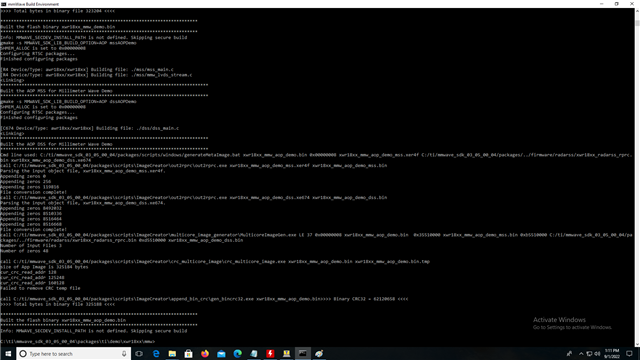
3. The same mmWave demo binary file given only has to be uploaded every time (or) Do we have to create a binary file to flash every time depending on need. If so how to create it.

     If you like ,please check the thread 1092373 in link:
   e2e.ti.com/.../4103559

   Sincerely Looking forward to your further support! Thank you very much!

Best Regards
Miao Bai
TI Customer Support Center

  • I see that other thread has gone for a long conversation.

    Flashing is going through, with that I;m expecting that you can see COM ports emulated in the PC when EVM is connected over USB cable.

    So when you are done with flashing in SOP5 mode (1 0 1) from UniFlash tool and then change the SOP settings to SOP4 (1 0 0) functional mode and power cycle the board.

    Now to verify this case, I would request you to try with some serial terminal (e.g. TeraTerm) instead of Demo Visualizer. 

    In TeraTerm (or any other serial terminal) you need to connect to 'Application/UART' COM port (as emulated under device Manager at 115200 Baud rate

    There you should see the OOB demo prompt like below

    This will prove that flashed application is booting well.

    Regards,

    Jitendra

  • Hi Jitendra,

        Good day!

        Thanks for your further support!

       The customer have tested by the TeraTerm just like we suggested, but it failed also and reply in the thread 1092373 :

       "1. Loaded the EVM with xWR1843_ccsdub.bin in uniflash to work in CCS debug mode.
        2. Changed the SOP jumpers to functional mode.
        3. Opened the Teraterm window. In Setup -> serial port I choose the UART port (COM 22 in my device) and the baud rate 115200 and , and transmit delay to 0msec/char, 500msec/line.
       4. Opened the another Teraterm window. In Setup -> serial port I choose the data port (COM 21 in my device) and the baud rate 921600 and , and transmit delay to 0msec/char, 0sec/line.
       5. Pasted the config file commands given by him 'xwr18xx_profile_2022_04_20T14_56_41_886.cfg' in the Terterm.
       6. All instructions are executed. I can't see skip or done. Instead I seen other numbers beside the sensorStart
    command.
       7. I went to the data port window. I can't seen any other data.
    "

      After these response , the support engineer changed to the others, and no further suggestion for the testing in Teraterm.

    Best Regards
    Miao Bai
      

  • Here is modified steps that need to be followed

      "1. Loaded the EVM with xWR1843_ccsdub.bin in uniflash to work in CCS debug mode.
        2. Changed the SOP jumpers to functional mode and power cycle
        3. Opened the Teraterm window. In Setup -> serial port I choose the UART port (COM 22 in my device) and the baud rate 115200 and , and transmit delay to 0msec/char, 500msec/line.
       4. Opened the another Teraterm window. In Setup -> serial port I choose the data port (COM 21 in my device) and the baud rate 921600 and , and transmit delay to 0msec/char, 0sec/line.

    5a. Load application debug image via CCS to R4F and C67x core, in case of mmw demo these are the files

    C:\ti\mmwave_sdk_03_05_00_04\packages\ti\demo\xwr18xx\mmw xwr18xx_mmw_aop_demo_mss.xer4f and xwr18xx_mmw_aop_demo_dss.xe674, that you need to load via CCS to AWR1843 device.

    Follow section '3. 2. 2. CCS development mode' from C:\ti\mmwave_sdk_03_05_00_04\docs\mmwave_sdk_user_guide.pdf

    After loading the image, run DSS (C67x) core first then run MSS (R4F) core, it should print the demo command over TeraTerm.


       5b. Pasted the config file commands given by him 'xwr18xx_profile_2022_04_20T14_56_41_886.cfg' in the Terterm.
       6. All instructions are executed. I can't see skip or done. Instead I seen other numbers beside the sensorStart
    command.

    Command should be sent same as given cfg file else application running on AWR device will throw an error.
       7. I went to the data port window. I can't seen any other data.

    Regards,

    Jitendra

  • Hi Jitendra,

       Thanks for your support!

       I'll ask the customer to check and reply you if I get the test result  .

    Best Regards
    Miao Bai 

  • Hi Jitendra,

        Greetings for the Day! 

        My customer try to run the  DSS (C67x) core  and MSS (R4F) core, but he failed get data also. I post his test progress, please kindly give some suggestion:

       1) In step 5(a) , you told to upload the "xwr18xx_mmw_aop_demo_mss.xer4f" and "xwr18xx_mmw_aop_demo_dss.xe674".

          But my device is not AOP. So I uploaded and ran "xwr18xx_mmw_demo_dss.xe674" first and then "xwr18xx_mmw_demo_mss.xer4f".
          Both DSS and RSS are running simultaneously. (Fig. 23)

         It printed the mmwDemo command over UART port (COM 7 in my device) (Fig. 23) .


         It did not print anything on data port (COM 6 in my device) (Fig. 22).


     2) I copied and pasted "xwr18xx_profile_2022_04_20T14_56_41_886.cfg" on UART port (Fig. 24).


    It printed '%' is not recognized as a CLI command. (Fig. 25)


    So I copied from SensorStop in the "xwr18xx_profile_2022_04_20T14_56_41_886.cfg" file. (Fig. 27)


    Pasted them on UART port, nothing is displayed. (Fig. 28)


    Pasted them on data port, nothing is displayed. (Fig. 29)

    3)I again tried Ran both DSS and MSS simultaneously.
    But It did not print mmwDemo on Teraterm UART port and data port
    I tried to paste profile_3d.cfg from "C:\ti\mmwave_sdk_03_05_00_04\packages\ti\demo\xwr18xx\mmw\profiles"
    I pasted it on UART port in teraterm.It is continuously printing some letters like in Fig. 30.

    Looking forward your further support! Thank you so much!

    Best Regards
    Miao Bai 

  • Hi Jitendra,

       In addition, we do not know how the response in Teraterm looks like. Could you kindly explain what is right response in Teraterm?

       Thank you so much!

    Best Regards

    Miao Bai

  • Hi Miao,

    I see in MSS goes into ASSERT in the CCS.

    So with this error application won't run and it doesn't respond to the CLI command you send over TeraTerm.

    Based on old response here, I'm not certain if customer has tried yet flashing the

    C:\ti\mmwave_sdk_03_05_00_04\packages\ti\demo\xwr18xx\mmw\xwr18xx_mmw_demo.bin  file to the device using UniFlash tool.

    If not please try flashing this file to device and connect TeraTerm the same way you have done above.

    Application/UART com port is used to send CLI command (*.cfg), send one command at a time (for now to test). Other Auxiliary COM port is to get the object data from Device as soon as you send sensorStart command via CLI com port, so this (auxiliary) com port doesn't accept any data (No TX) but only RX.

    And I would request customer to follow the exact instructions provided in C:\ti\mmwave_sdk_03_05_00_04\docs\mmwave_sdk_user_guide.pdf (section#3), all the steps to flash and run the application are provided there.

    Regards,

    Jitendra

  • Hi Jitendra,,

       Good Day!

       Please check the response from my customer for your further suggestion:

      1) I followed all the instructions in mmWave SDK user guide. I again tried the CCS mode as he told.

    Both 'Application/User UART port' and 'Auxiliary Data port' are connected in Teraterm.
    I have seen the "mmwDemo" command in Application/User UART port in Teraterm as soon as I ran DSS (C67x) core first then run MSS (R4F) in Code Composer Studio.
    I have copied and pasted "xwr18xx_profile_2022_04_20T14_56_41_886.cfg" in Application/User UART port in Teraterm. All instructions are executed. I have seen "Done" command in Application/User UART port in Teraterm against all the instructions. 


    But when all the instructions executed, the Auxiliary Data port is showing it is disconnected in Teraterm

    2) I have performed the demonstration mode.
    I flashed the device with "xwr18xx_mmw_demo.bin" in C:\ti\mmwave_sdk_03_05_00_04\packages\ti\demo\xwr18xx\mmw. The flashing is successful.
    I changed SOP pin to on and powercycled the device. Connected the COM ports in mmWaveSDK application


    Pressed the LOAD CONFIG FROM PC AND SEND from Plot section and uploaded profile_3d.cfg from "C:\ti\mmwave_sdk_03_05_00_04\packages\ti\demo\xwr18xx\mmw\profiles".
    All the instructions are showing "Done" in Console Messages. But it is popping up "Error" and also showing "Hardware disconnected" 


    I tried sending commands using "SEND CONFIG TO MMWAVE DEVICE" from configure section. Same error is popping up and showing "Hardware disconnected" 

       Could you kindly suggest how to resolve it? 

    Best Regards
    Miao Bai 

  • Hi Jitendra,

        Good day!

        Do you have any suggestion for my customer's test result?

        Looking forward your further support! Thank you so much!

    Best Regards
    Miao Bai 

  • Hi Miao,
    So as I can see from the the cores are disconnecting.
    So could you please tell the customer to try out the following steps:
    1) Connect the device to the pc and then try the CCS mode. 
     He can then connect to the R4 and then the C67 core, then load the .xer4f and .xe674.
     2) Once he has done this, he can load the code on both the R4 and C67 respectively.
     Then once it loads successfully, he should be able to open the mss main file which is going to run on the R4.
     3) Once he is able to access this particular file, he has to set a break point at a function named 
    MmwDemo_openSensor
    and then set a breakpoint at line 2946 ( in 3.5 sdk it is the first line of code after the MmwDemo_openSensor function in mss_main.c)
    4) He can set a breakpoint by right clicking the particular line and select the breakpoint option.
    5) Then as usual he needs to send the particular cfg files and follow steps in ccs mode. If the breakpoint is set correctly, the code should stop at that point.
    6)Then he needs to step into the code line by line to debug where exactly is it throwing the error, so that we can also get more clarity as to what is the issue.
    Please do tell the customer to share the image which line is he encountering the error and what the error is.

    Regards,
    Saswat Kumar

  • Hi Saswat,

        Good day!

        Thanks for your support!

        Why the core disconnected? The customer follow the suggestion from Jitendra , and test step by step in CCS mode, and get the error listed upside. 

         Regarding your suggest:

        1. In step 2, the configuration files means xwr18xx_mmw_demo_dss.xe674" "xwr18xx_mmw_demo_mss.xer4f". Or other?
         2. He wants to me to modify MSS file in CCS after loading and before running right?
         3. No need to modify DSS file right?

    Best Regards
    Miao Bai 

  • Hi Miao,
    To find out why it is getting disconnected, we need the user to step into the code to help debug.
    1) Yes those are the files to be loaded on the core.
    2) So setting a breakpoint is not modifying the code. But yes, the breakpoint needs to be set once he has loaded the code. Then run the code, send the .cfg file with the commands over the tera term in Application Uart. It should hit the breakpoint after this.
    3) No need to modify the file in DSS
    Regards,
    Saswat Kumar

  • Hi Saswat,

        Thanks for your quick response.

        I'll post the  test result from customer later.

    Best Regards
    Miao Bai 

  • Hi Miao,

    Also there was a typo in the previous thread, I have retyped it so that the user can follow it properly.
    Do forward him the edited one as highlighted in the quoted thread.

    He can then connect to the R4 and then the C67 core, then load the .xer4f and .xe674.

    Regards,
    Saswat Kumar

  • Hi Saswat,

        OK,  I get it .

    Best Regards
    Miao Bai 

  •  Hi Saswat,

        Good day!

        My customer have followed your suggestion and it seems no new progress for the issue. Could you kindly check his response and suggest us further?Thank you so much!

    "

    I have done as Saswak said.
    Here are the screenshots with stpes

    1. Connected in CCS debug bode using Uniflash.
    2. Changes SOP to functional and connected to both UART and Auxiliary data ports in Teraterm
    3. Connected and loaded both R4 first and then the C67 cores. (Fig.1)


    4. Set the break point in MmwDemo_openSensor function at line 2946. It is showing breakpoint is at 2955. (Fig. 2, Fig. 3).


    5. Ran C67 first and then R4 next. (Fig. 4).


    6. In UART port at teraterm , it has printed mmwDemo (Fig. 5)


    7. Copied and pasted the configuration files in UART port. All instructions are showing Done. (Fig. 6).


    8. Unlike last time the Auxiliary data port is not disconnected (Fig. 7), but it is not showing data. (Fig. 7).

    Best Regards
    Miao Bai 

  • Hi Miao,

    Then he needs to step into the code line by line to debug where exactly is it throwing the error, so that we can also get more clarity as to what is the issue.

    The user needs to step into the code line by line, in the screen shot attached he has not stepped in after the first line 2955.
    There will be no output as the user has not stepped into the code and executed it.
    Do tell the user to step in and find out the point where the core is getting disconnected or throwing error.
    Then attach similar screen shot once he know which line is throwing the error so that we can debug.

    Regards,
    Saswat Kumar

  • Hi Saswat,

        Good day!

       Could you help to explain clearly about the customer confusion?

    I don't know how to debug line by line.
    Do I have to use "step into". If so
    1. Do I have to press "Step Into" it once at the starting line or at every line?

    2. do I have to press it at the start of the code in first line of the code (or) at the MmwDemo_openSensor function at line 2944. "

    3. whether I need to use "step into" function while running the both the cores ( after step 5 he told.i.e after sending cfg files in teraterm)?

    Best Regards
    Miao Bai B

  • Hi miao,


    There are three buttons that the user can see on the screen, the first one is step into, the next step over and the last step return. They are in the same order in the image as well.
    The step into is the one that goes line by line into every function. The step over will execute each function as you keep clicking it. The step return will execute the whichever function it currently is in and return back to the code.

    So once the breakpoint is set, the user can run the code until that point. Once the breakpoint is hit, the user needs to step into the code line by line to see which line of code is causing the core to get disconnected. 
    So basically step into needs to be used at MmwDemo_openSensor function at line 2944.
    Then attach the similar screen shots and we can debug further.

    Regards,
    Saswat Kumar

  • Hi Saswat,

        Good day!

       There are debug result from my customer , please help to check and advise us, thank you so much!

       I pressed "step into" at line 2944, it has given Fig. 8.


       I pressed "step into" at line 2955, it has given Fig. 9.


    I pressed "step into" at line 2958, it has given Fig. 16.  After that every line is giving Fig. 16

    Best Regards
    Miao Bai

  • Hi Miao,

    When its stuck at the line 2958, even if there is a step return given or step over is it still stuck?
    If not can you try clicking step return and step over, then send the screenshots after the process of clicking both step return or step over? 
    If it goes back to the main code and starts executing the line after that and resumes normally, then keep stepping in until you hit the error and then attach the screen shot.

    If you see that step return or step over is also not getting executed, then we can go further into what is causing the function not to return a value.

    Regards,
    Saswat Kumar 

  • Hi Saswat,

        Good day!

        My customer has followed your suggest, and test result is listed below, please check it :

    After it got stuck at line 2955 as in Fig. 16 like last time.I pressed 'Step Over' at 2955. It still showing the same Fig. 16.


    When I pressed 'Step Return' at line 2955. It is giving Fig.17.


    So I pressed 'step into' or ' step over' at line 2963. It is giving Fig. 18.


    When I pressed 'Step Return' at line 2963. It is showing error.


    I performed the same operation from the start three times. Upto Fig. 18 same response shown in above steps happened.

    But When I pressed 'Step Return' at line 2963. It is showing errors as in Fig. 19, Fig. 20, Fig. 21"

    Best Regards
    Miao Bai

  • Hi miao,

    Could you ask the customer which version of sdk he is utilizing?
    Also is he using the AWR1843 EVM or is it a custom board?

    Regards,
    Saswat Kumar

  • Hi Saswat,

         Good day!

         My customer test with platform:.     AWR1843BOOST + mmWave SDK version 3.5.

         Do you sure what is the root cause  now? This issue has troubled us for nearly half a year.

         Thank you so much!

    Best Regards
    Miao Bai

  • Hi miao,

    I tried to replicate with the same setup, but I am unable to recreate the same issue as its working for me.
    So next step that we can go for I have listed down below, do tell the user to follow the steps:

    1) When the user is stepping in and stopping on this particular step ( I have attached the picture as well) 


    2) In this part, press the locate file option that is present in the window

    3) Here you will have to select the folder where these folders are present, here go to the folder 
        C:\ti\mmwave_sdk_03_05_00_04\packages\ti\control\mmwavelink and then select the src folder in this       directory.

    4) This is should allow you to see the file rl_sensor.c, after this follow the same steps on stepping in and checking which of the function call is causing the issue.

    Do attach the screenshot similarly.

    Regards,
    Saswat Kumar

  • Hi Saswat,

        Good day!, Thanks for your support! Please check my customer's test result:

    I selected and located the files after getting like in Fig. 16.

    Located the src folder as the path specified by Saswat. It is still not locating the "rl_sensor.c" and giving the same result as Fig. 16. (Fig. 24, Fig. 25)


    I performed the same way by locating after getting like in Fig. 9. It is also not locating the corresponding file and giving the same result as in Fig. 16.(Fig. 22, Fig. 23)


    like last time, I pressed step return at line 2963. It is giving errors like last time in Fig. 21.

    Best Regards
    Miao Bai

  • Hi Miao Bai,

    Can you tell the customer to try commenting out certain parts of the code in the mss_main.c.
    I have attached the screen shot below as well, let the customer make the changes


    After making the changes, the user needs to rebuild the demo as well and this information on how to rebuild can be found in 
    C:\ti\mmwave_sdk_03_05_00_04\docs\mmwave_sdk_user_guide.pdf
    In this the section 4.5.3 Building demo talks about how to build the demo.
    After making the changes the user needs to rebuild the demo and then can attach the screen shots in case they see any other issue.

    Regards,
    Saswat Kumar

  • Hi Saswat,

        Thanks for your support!

        For your suggestion, the customer has further confusion:

    "Whether I need to edit the "mmw xwr18xx_mmw_demo_mss.xer4f" file in notepad as he told and save the file, then build the demo without the device attached to pc and Post these screenshots."

        Please check his test result also: 

      " I did it CCS from the start. i.e. After flashing, connected Teraterm ports and opened CCS .

        I connected R4F core and C67x core. Loaded MSS and DSS files respectively. Edited "mss_main.c" file as he asked (Fig.26).


    I did not ran the R4F and C67x cores. I went for rebuilding the demo as told in 4.5.3 in user guide.
    Opened the command prompt and changed the directory to C:\ti\mmwave_sdk_03_05_00_04\packages\scripts\windows as told in section 4.5.2.1 in mmWave sdk user guide. (Fig. 27)


    Ran setenv.bat and showed "mmWave Build Environment Configured" (Fig. 28)


    Then I copied the commands as told in 4.5.3.1 (Fig.29)


    Ran these three commands. It stopped at gmake all command (Fig. 30)


    Pressed enter . IT resulted Fig. 31 "


    Best Regards
    Miao Bai

  • Hi Miao,

    So the steps I mentioned in the previous reply are checked as I have cross verified it myself.
    Firstly, I would request the customer to go over this entire thread once more and see if he has followed the exact steps in all process.
    I would also suggest the user to redownload the mmwave sdk 3.5.0.4 again and also the ccs 1100 and follow the steps exactly I have mentioned below

    1) Open the setenv.bat file in any code editor like visual studio code or notepad from C:\ti\mmwave_sdk_03_05_00_04\packages\scripts\windows and then 

    In line 12 set he mmwave sdk to the one set in the above image

    2) Then the user can go to C:\ti\mmwave_sdk_03_05_00_04\packages\ti\demo\xwr18xx\mmw\mss\mss_main.c and make the same comment changes that I have posted in the picture below


    3) After making these changes the user needs to rebuild the demo as they have done in the previous step and this information on how to rebuild can be found in 
    C:\ti\mmwave_sdk_03_05_00_04\docs\mmwave_sdk_user_guide.pdf
    In this the section 4.5.3 Building demo talks about how to build the demo.

    "Whether I need to edit the "mmw xwr18xx_mmw_demo_mss.xer4f" file in notepad as he told and save the file, then build the demo without the device attached to pc and Post these screenshots."

    You should not edit the .xer4f file as these are build files and are the ones that are generated when you give the command gmake all

    4) After rebuilding, the follow the steps mentioned to load the .xer4f and the .xe674 on the mss and dss cores utilizing the CCS studio which is installed.
    Then check whether it is working. If not again try the debug process steps given above and provide the screenshots in case of errors.

    Regards,
    Saswat Kumar

  • Hi Saswat,

        Good day!  Thanks for your support!

        My customer still have some confusion about your suggest:

         1) In step 4 , could you kindly help to explain " the  debug process steps " detailed?

        2)  " do I have to build the demo after flashing the device or before flashing the device?"

       Thank you so much!

    Best Regards
    Miao Bai

  • Hi miao,

    So the entire thread has the information on how to debug, it includes how to use the step in, step over and other functions available in the CCS studio.
    I would request the user to go over it again, and also other material on the Ti websites for basic information on the board and how to use the various functionalities. Also on the e2e and the user guide for the AWR1843, the user can go over various other topics, which will help build a good understanding.
    Also, i would request the user to through this document in detail as it has all the information,
     C:\ti\mmwave_sdk_03_05_00_04\docs\mmwave_sdk_user_guide.pdf

    The demo needs to be built before flashing the device.

    Regards,
    Saswat Kumar

  • Hi Saswat,

        Good day! Thanks for your support!

       My customer also wonder that he debug in CCS 12 , is it ok?

    Best Regards
    Miao Bai

  • Hi Miao,

    It is possible but requires changes, but would recommend using the ccs 1100 for the particular sdk.

    Regards,
    Saswat Kumar

  • Hi Saswat,

        Good day!

        My customer followed your suggestion, and test with  SDK v3.5.04 + CCS v11, please check his test result and suggest us how to resolve the issue, thank you so much!

    Edited the setenv.bat and mss_main.c files as he told (Fig. 32, Fig.33)


    Builded the demo as told in User guide (Fig. 34, 35,36).

    It resulted Fig. 36


    Flashed the device, Changed to functional mode and then connected ports in teraterm.

    Opened CCS and ran C67x first and then R4F. Pasted the instructions from xwr18xx_profile_2022_04_20T14_56_41_886 in Application/UART port in Teraterm. Nothing seen at Auxillary Data Port.(Fig. 37,38)


    I suspended C67x, R4F cores from running. Pressed Step into at line 2944. It resulted Fig. 42.

    Step Over at line 2944 resulted same Fig. 42. Step return at line 2944 resulted Fig. 43.

    Again applied step return at 2944 it resulted 44.

    Again spplied step return at 2944. It resulted Fig. 45.

    I tried applying step over /step return/step into at line 2992. all of them are showing any one of the lines in idle.c shown in Fig. 43 and 44

    Best Regards
    Miao Bai

  • Hi Saswat,

        Good day!

        Could you help to check the test result from the customer  upside? Is there any suggestion?

       Thank you so much!

    Best Regards
    Miao Bai

  • Hi Miao,

    Let me check this and get back to you.

    Regards,
    Saswat Kumar

  • Hi Miao,

    Could you ask the customer, to make the below changes in the mss_main.c and then follow all the above steps of rebuilding and then load it on the cores on the AWR1843 device and check if its giving error?

    Also everytime after running the demo, do press the nreset(SW2) button on the EVM and connect to the cores again and then load it and execute.


    Regards,
    Saswat Kumar

  • Hi Saswat,

        Thanks for your support!

        My customer has some confusion about your suggest upside, could you kindly help to explain detailed? Thank you so much!

       " what I don't understand is 'after running mss_main.c and dss_main.c, pasting the cfg files to teraterm' means demo is run'. These are the last steps.
    Should I press sw2 here before executing step return/over/into instructions. this is all done after connecting the cores and lording the cores.
       I am thinking he may have meant after building demo.

       Could you ask him does he meant building the demo? , if not, what is running demo means,
    and point at what step should I press SW2? " 

    Best Regards
    Miao Bai

  • Hi Miao,

    So after pasting the CLI commands on the tera term, to you are starting the sensor and that means the sensor has started. Then if you will notice data in the demo visualizer and then you will know that the demo is running.
    After this you need to disconnect the core, then you  are supposed to nreset and press the SW2 button. What is does is resets the core.

    Now after this you will need to connect, then you load the the built files on the cores and execute it on CCS.

    Regards,
    Saswat Kumar

  • Hi Saswat,

        Thanks for your patiently support!

       My customer has  one question further , please check ,thank you so much!

      " When I am connecting the device UART and Auxiliary data ports to Teraterm, I am not connecting the device to mmWave Demo visualizer.

       But He said notice data in demo visualizer. I am thinking He meant data in the Auxiliary data port in teraterm.

      please clarify you  actually meant mmWave Demo visualizer or Auxiliary data ports in Teraterm ? "

    Best Regards
    Miao Bai

  • Hi Miao,

    So if the user is connected to ports via tera term, then the  user cannot connect to the mmwdemo visualizer as the ports are already connected.

    Could you ask the user, to not connect to tera term and only use demo visualizer. Also ensure that the baud rates are set properly for the application port to 115200 and for the data port to 921600.

    If the user is able to work the demo, then I think the users issue should be resolved and this thread can resolved.

    Regards,
    Saswat Kumar

  • Hi Saswat,

        Good day!

       Please kindly help to check  the test steps my customer followed and suggest us further. Thank you so much!


    Edited the and mss_main.c files as you told (Fig. 46)


    Builded the demo as told in User guide (Fig. 47, 48,49).

    It resulted Fig. 49


    Flashed the device, pressed sw2 on EVM multiple times. Changed to functional mode and then connected ports in mmWaveSDK visualizer (fig. 50)


    Opened CCS. Connected to C67x (fig. 51 resulted).

    Connected R4F (fig. 52 resulted).


    Loaded DSS file on C67x (Fig. 53 resulted)

    Loaded DSS file on R4F (Fig. 54 resulted)


    ran C67x first and then ran R4F. Tried to upload the cfg file in mmWave SDK visualizer using load config from PC and SEND (Fig.55).


    I could not see any commands in console messages (Fig.56). So it is not taking cfg file. I tried pressing 'SEND CONFIG TO MMWAVE SDK'. still it is not taking any instrunctions.


    Then I saw the CCS . It is showing Fig. 57.


    I pressed SW2 on EVM it sulted Fig. 58.

    Best Regards
    Miao Bai

  • Hi Miao,

    Could you ask the customer to show me which file he is loading on the mss R4f?

    It doesnt look like the customer is actually loading the correct file as it doesnt show main() at mss_main on the R4f core
    Also can you build the files once more and ensure that you are loading the files you built itself? 
    Send a picture of of the files you are loading and what your ccs looks like after loading the files. it should both show starting at main code for each core.

    Regards,
    Saswat Kumar

  • Hi Saswat,

        Thanks for your support!

       As you required, my customer update the screenshot , please check it:

    " For C67x (Fig. 59).

    It resulted Fig. 60 in CCS.


    For R4F (Fig. 61).

    It resulted Fig. 62 in CCS.

    One thing I did not tell before is when editing the 'mss_main.c' file, I observed this (Fig.63)."

    Thank you so much!

    Have a great day and keep safe at all times.

    Best Regards
    Miao Bai
    TI Customer Support Center

  • Hi Miao,


    Also once you connect to the core can you press the reset button before loading the file on the core:

    Before loadig the mss code, 
    1) reset by pressing the buttton

    Then after pressing this button, load the code and then run the R4f core.

    Regards,
    Saswat Kumar

  • Hi Saswat,

       Good day!

       My customer test as you suggest ,please check his result:  


    " Builded demo, flashed the device, changed to functional mode and connected to mmWave SDK.
    Opened CCS. Connected to both the core and loaded DSS into C67x core.

    Pressed reset button. It appeared like in FIg. 64.


    Loaded MSS into R4F core. Fig. 65.

    Thank you so much!

    Have a great day and keep safe at all times.

    Best Regards
    Miao Bai

  • Hi Saswat,

        update continued from the customer:

       I have again pressed reset button in CCS. It showed Fig. 65b.

    Loaded MSS file into it. MSS_main.c is visible now. Fig. 66.


    Ran both the cores Fig. 67.

    In mmWave SDK console message pallet showing Demo command. Fig. 68.


    pressed SEND CONFIG TO MMWAVE DEVICE. The hardware disconnected. Fig.69.

    Then In CCS it appeared Fig. 70.

    Again I pressed SW2 on EVM as you said before when demo is performed.Connected mmWave SDK. Fig.71.

    Connected both the cores. Loaded DSS into C67x. Fig. 72.

    Pressed reset Fig. 73.

    Loaded MSS Fig. 74.

    Just like before mmWave SDK console messages showing command. Fig. 75


    THis time loaded the config file using LOAD CONFIG FROM PC and SEND. Hardware disconnected again Fig. 76.

    CCS shown Fig. 77.

    Now pressed SW2 on EVM. Connected both the cores and loaded DSS to C67x and pressed reset on CCS and loaded MSS. Ran C67x only. everything shown just like above.

    Best Regards
    Miao Bai

  • Hi Saswat,

        The last update  from the customer:

        Pressed 'Step into' at 2944 in MSS. Fig. 78 resulted. again pressed Step into at 3951.

    Fig. 79 resulted.

        
    Pressed 'Step over' at 2944 in MSS. Fig. 80 resulted.


    Pressed 'Step return' at 299 in MSS. Fig.81 resulted.

    again pressed 'Step return at 3954. Fig. 82 resulted showing both the cores are running.. Console messages in mmWave SDK shown Demo command.Fig.83.

    pressed SEND CONFIG TO MMWAVE DEVICE. The hardware got disconnected. Fig. 84.

    CCS shown errors Fig. 85.

    Please kindly check test result from the customer in 3 replies today.  Thanks a lot. 

    Best Regards
    Miao Bai

  • Hi Saswat,

        Good day!

        In addition,  for 'Invalid response was received from XS110.'. the customer searched in E2E and found there are so many posts like this.

        He don't understand the terminology, but some of them showing resolved. 

    Best Regards
    Miao Bai

  • Hi Saswat,

        Good day!

        Any suggestion for new update test result?

       Thank you so much!

    Best Regards
    Miao Bai