This thread has been locked.

If you have a related question, please click the "Ask a related question" button in the top right corner. The newly created question will be automatically linked to this question.

TDC1000-C2000EVM: TOF value not changing no matter how height the water level is

Part Number: TDC1000-C2000EVM
Other Parts Discussed in Thread: TDC1000

Hi,

I need some help here, I had search thru the forum which related to my questions, I found out there are quiet a few thread didn't conclude or there is not solution can be found on the thread.

for example

TDC1000-C2000EVM: use TDC1000 + transducer ( ultrasonic ) to sense the water level of a plastic container from outside.

TDC1000-C2000EVM: Application using TDC1000 for measuring water level in tanks

TDC1000-C2000EVM: TOF value not changing with the water level


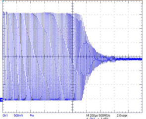
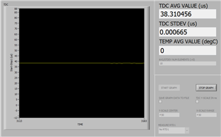
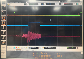
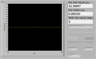
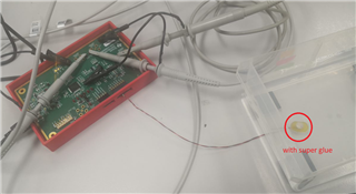
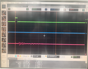
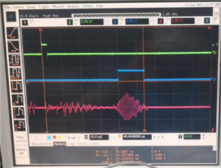
i had tried few type of containers but the all the TOF constantly remained around 38us. i am using  SMD15T21R111WL. (1Mhz)

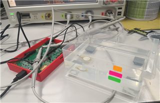
after that I print out a 30mm x 30mm x 50mm container as shown in the picture below and test it.

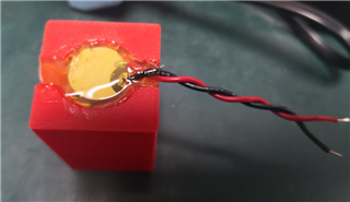
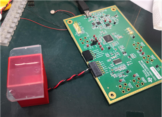
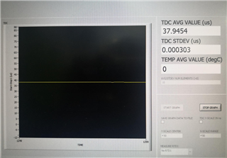
the TOF not changing no mater how height the water level is.

thanks,

Chin

  • Hello Chin,

    Thanks for posting to the sensing forum! This is a common problem when using the TDC1000 device, the main reason why users typically do not see the time of flight changing is due the configuration of the listening window. As mentioned in the related question you linked at the top.

    If you notice the ToF listed here is ~38us. If we convert this ToF to a distance assuming a 1480 m/s speed of sound in water we can use the following formula:

    distance= (ToF*speed of sound)/2   or distance = (37.94us*1480)/2, which equates to about 2.8cm.

    This typically indicates the listening window is configured incorrectly and is listening to the echo far too early. I have included an image below for better depiction, but when an ultrasonic transducer is excited the voltage on the AFE will saturate and the transducers voltage will decay (commonly referred to as the ringdown period). If you device is set to listen during this ringing period it will accidentally trigger the threshold generating a false STOP signal on the device. The main goal would be to configure the device to listen after this period has completed in order to avoid any false detection.

    I am not sure what distance you are trying to measure in your system but the TDC1000 has a standard ToF measurement mode as well as a Short ToF measurement mode (please refer to section 8.4.6 of the datasheet). Each of these has different registers that can be configured to tell the device when it needs to ignore signals from the AFE and when to begin listening to them in order to generate a STOP signal. Check section 2.2.4 of this FAQ for some an example on how to configure this listening period: https://e2e.ti.com/support/sensors-group/sensors/f/sensors-forum/724028/faq-tdc1000-everything-you-need-to-know-for-ultrasonic-tof-liquid-coupled-collateral-tools-designs-faq

    Let me know if there are any questions!

    Best,

    Isaac

  • Hi Isaac,

    I will try to play ard with short Tof measurement mode and come back to you after that, thank you very much

    Rgds,

    Chin

  • Hello Chin,

    Of course, please let me know if any other assistance is needed.

    Best,

    Isaac

  • Hi Isaac,

    i wanna confirm with you on the on wire connection, TX1 >> positive + transducer and Gnd >> negative - transducer for water tank level sensor correct?
    also does the CA glue is necessary to apply? 

    thanks,

    Chin

  • Hello Chin,

    That is correct, I confirmed your connections were correct when you submitted the post. Make sure you have the correct channel is selected as well as the listening mode. If the wrong is selected the device will try to listen on the wrong TX and RX combination on the board. 

    The CA glue is necessary because we need to ensure good mechanical connection to the tank. Without this mechanical adhesion the signal might not travel through the tank and just be reflected by it instead. CA is just super glue so it should be fairly easy to find.

    Best,

    Isaac

  • Hi Isaac,

    ya, currently i am using TX1 channel.

    the reason i didnt applied the super glue is that i still havent finalize the tank dimension, i wanna save the transducer for the final tank.

    thanks,

    Chin

  • Hello Chin,

    Thanks for the confirmation. This could be the source of error you are getting, since the transducer is not making proper connection with the tank the wave is not propagating through the system appropriately. You might have to begin testing once you have finalized your tank dimensions and printed a new tank.

    Best,

    Isaac

  • HI Isaac,

    may i confirm with you with 1 thing, can i say that there is no other way that we can test it without using super glue (proper connection) to the tank? 
    if let say i put the transducer at the bottom without any super glue, just use my finger to press it, will this also cause the error i am getting it?

    thanks,

    Chin

  • Hello Chin, 

    Sorry for the delay.  We are just coming back from the holidays.  Isaac should be able to take a look at your most recent questions tomorrow.

    Regards,

    Mekre

  • Hello Chin,

    Thanks for the patience as we were out of office for holiday. But I have tried this in the past and have not had good success by simply pressing the transducer into the tank. It is also possible that you still have not configured your listening window correctly. If you provide me the water level you are trying to measure as well as the speed of sound in the liquid you are trying to measure I can try to suggest some settings.

    Best,

    Isaac

  • HI Isaac,

    my plan is to try out to different tank small container and medium/large container, i will share you the small container first. 

    110mm x 140mm x 58mm (height)
    1M 15mm steminc transducer

    water level 
    20mm (green sticker)
    30mm (pink sticker)
    40mm (orange sticker)

    i got ard 38us for all these 3 layers


    thanks,

    Chin

  • for big container, i am just using normal water 

    128mm diameter 
    160mm height

    water level 
    50mm (green sticker)
    100mm (pink sticker)
    150mm (orange sticker) >> did not try

    i got ard 52us on both level (50mm and 100mm)


    seem like i am not getting the real source or echo form the transducer correct?

    thanks,

    Chin

  • Hello Chin,

    For your small tank you didnt mention what the speed of sound would be or the type of liquid you are measuring so I just assumed water. That means your ToF should be approximately 27us-54us (20mm-40mm) with your current settings you are not actually listening to the echo until about 36us which means you would never be able to capture your shortest ToF. Here are my settings for ~22.5mm of water achieving a 30.5us ToF.

    For your large tank your ToF should be approximately 67us-202us (50mm-150mm) so the standard ToF is fine for this tank since you begin to listen at about 52us, you could probably reduce the time of listening window but keeping it large shouldn't be a problem.

    If you notice both of your measured times are triggering pretty much right after they activate 38us for your small tank when listening starts at 36us and 52.5us when your listening starts at 52us. Meaning that you could have more than the required gain on here or that you are accidentally triggering on the ringing. But both of these are false measurements. I would try to probe your transducer connection to see what you could be possibly be measuring. If you noticed for my small measurement I turned off the PGA since the measurement is so small you do not require that much gain. Although I still believe that part of the problem is the way the transducer is mounted to the thank.

    I hope this helps!

    Best,

    Isaac

  • HI Isaac,

    yup, you are right both are using water. i had tried the setting you has suggested above but still failed. 

    anyway i managed to find a BPU-P7-1000B-W200 (7mm 1Mhz) transducer to be to scarified for this experiment. i had applied with super glue than follow up with hot glue gun.  

    the TDC value not stable (random number in us) and there is no stop signal to be found in the scope below


    any idea? seem like the connection between the transducer and the tank is not as easy as i think. 

    may i know what kind of tank/material you are using?

    thanks,

    Chin

  • Hello Chin,

    I am using an acrylic tank kind of like the one pictured in this document but bigger. If the tank you are using is not one solid material and has air gaps in between this could be very problematic for the ultrasonic signal since it would get deflected as it reaches the next material boundary.

    I am assuming your markers are where you expect the stop signal to be and is the pink signal your COMPIN output?  Whats the level being measured here?

    Best,

    Isaac

  • HI Isaac,

    The markers was from previous measurement, yes the pink signal is the comp in output, the level is ard 20mm-23mm.

    thanks,

    Chin

  • Hello Chin,

    Thanks for the info, small measurements in this range can be pretty difficult to make, my suggestion would be to increase the level a bit and try to do a larger measurement first then work your way to a lower measurement.

    I would also recommend probing the TX signal over the START pulse just so that you can see the burst profile. The comparator looks like its activating at the proper time but the signal that I believe to be the echo looks rather small, this might require some more gain or perhaps try increasing the amount of pulses to increase the measurement SPL. 

    Best,

    Isaac

  • HI Isaac,

    thanks for the suggestion. 
    I will try to probe the TX signal next week.

    another question, ABS material print out from the 3D printer is okay to use right ? if yes what is recommend thickness

    thanks,

    Chin

  • Hello Chin,

    I have not tried ABS before, but I believe it should work if you have the infill set to 100%. If you have the infill set to a lesser value there might be some airgaps between the outer walls which the ultrasonic energy would have to travel through. I think 3mm might be a good place to start and seeing if that is able to carry the signal across the material. Observing the COMPIN signal at your point of interest will be the best indicator of how the signal is traveling through the tank. If the signal is really weak or you are not getting anything try reducing the thickness.

    Best,

    Isaac

  • Hi Isaac,

    Good news, sorry for the late update. pls see the below picture

    currently i am only able to measure around 30mm-50mm of the water level due to the size limitation of the tank.

    another question, if let say i wanna connect this eval board to the other MCU, send this TOF/TDC to the other MCU, what is the best recommendation?

    or we should only connect start and stop to the GPIO will do?

    thanks,

    Chin

  • Hello Chin,

    That's great to hear, I am glad we were able to get this working for you! If you want to connect to another MCU to just do the timing calculations for you but not handle the communications you can connect the START and STOP signals directly to a GPIO pin. I have seen some implementation where they use the same pin by connecting an OR gate and count the time between two pulses or use two separate GPIO pins and just count the time difference the two pins.

    Currently the C2000 on the board is handling the SPI communication, GUI communication, and the timing between the signals. I hope this helps!

    Best ,

    Isaac

  • Hi Isaac,

    May i know whether the eval board can be auto run? i mean without the need to connect to the GUI,

    thanks,

    Chin

  • Hello Chin,

    It can be somewhat auto-run. So you must first connect the EVM to the GUI and configure as needed. Then enable the continuous trigger button found in the TDC1000 tab. You can then shut down the GUI and the device will still be running. Keep in mind the EVM would still need to be connected to the computer but the GUI will not have to be running and once powered down you will need to restart the GUI, reconfigure, and enable continuous mode once again.

    You could technically remove the L1 inductor and populate a test point at U11, this would let you provide 5V power externally and this would allow you to configure the device using the GUI and unplug it from the computer without resetting the MCU, since power would be provided externally and not from USB  VBUS. But it would still required the EVM to be reconfigured after being power cycled.

    I hope this helps!

    Best,

    Isaac

  • Hi Isaac,

    thanks. my final goal for this experiment to is to get the water level detection running without need to plug it to the computer.
    i think this should consider a different topic. probably will be on firmware approach. 

    many thanks to you again.

    thanks,

    Chin