This thread has been locked.

If you have a related question, please click the "Ask a related question" button in the top right corner. The newly created question will be automatically linked to this question.

PGA460-Q1: Adding external op amps

Part Number: PGA460-Q1
Other Parts Discussed in Thread: TDC1000, PGA460

Is there any limitations on using external op amps?

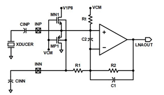
We have added low-noise external amplifiers before the INP pin in order to detect faint objects and in the hope that it will reduce noise.

(The one mentioned in the related question. The thread is closed so let me ask again.)

The attached is the voltage data we obtained for the input and output of the PGA460-Q1's amplifier (IN and OUT series). The OUT data were obtained using the Test pin output functionality.

The IN waveform being approximately triangular, and gain being high enough to have some porition of the waveform output saturate, I expected the OUT waveform to be approximately trapezoidal, frequency characteristics ignored. However, I have obtained the not-so-trapezoidal OUT waveform instead.

For comparison, I added the output data of the PGA460-Q1's amplifier when we did not use external amplifiers but with otherwise same conditions, with the gain of PGA460-Q1 adjusted to compensate for the missing external amplifer (sorry, no input data here). The waveform is trapezoidal as expected.

My question is, why are my OUT data deformed like this? And is this use of external op amps just before the input of PGA460-Q1 valid? My concern is that the external op amp's output is so strong that the PGA460-Q1's receiver circuit might get confused.

  • Hello user3263001,

    Thanks for posting to the sensing forum! This is a valid question but this not something we have seen used commonly with the PGA460 but instead with on our other devices TDC1000. The reason we see this being more commonly done with TDC1000 is because it has a very small dynamic range compared to some our other devices like PGA460 or TUSS44x0.

    This leads me to my main question, mainly trying to understand the use of an external amplifier. If the purpose is to use the external amp to increase the gain and reduce noise is there a reason why the TVG and digital gain amps in the device are not going to be used? Will the device be used in a form like this test where the TEST pin will output the data to be sampled by an ADC?

    My other questions are if you have sampled the data coming from the initial LNA you have created, is the data coming out as expected at this stage?

    Best,

    Isaac

  • Thanks for the reply.

    We have tested PGA460-Q1 on a pre-prototype, and noticed significant noise. Not sure about the source of the noise, we decided that instead of using the high gain settings of the PGA460-Q1, a combination of low gain settings of the PGA460-Q1 and external "low noise amplifiers" could reduce the overall noise. We also hoped that, if necessary, when combined with the higher gain settings of PGA460-Q1, there will be more gain for detecting faint objects (this is anyway a prototype for experimenting).

    For your second question, the answer is yes. I have verified the external op amps are working correctly, though not in the same conditions as in the figure attached (for the conditions in the figure, the voltage is too small, you know).

  • Hello user3263001,

    I am out of the office due to a US holiday, I will be back in on Wednesday and will review your reply then. I appreciate your patience!

    Best,

    Isaac

  • user3263001,

    Thanks for the additional information and comments. I am not quite sure what could be the issue here since I am not sure what signal is being fed to the PGA460-Q1 from your external LNA. Have you tried decreasing the gain of the external LNA stage to see if that has any effect on your perceived signal from the PGA460? This could help indicate if the problem is a gain problem too much gain or perhaps some sort of other problem between the LNA and the PGA460 input stage.

    Best,

    Isaac

  • I forgot to add that the external op amps are, like the one in PGA460-Q1, single supplied (5 V with 2.5 V Reference). Therefore, in the figure attached in the original post, if the oscilloscope were DC coupled, the IN signal would have been offset by 2.5 V. I suppose this would not cause any problem since there is a 390 pF capacitor before the INP pin.

    I also noticed that, in another instance, the gain obtained of PGA460-Q1 AFE seems like less than unity (like 0.4), while the setting was 32.5 dB. 

    As per your suggestion, I have tried with the unity gain of the external op amps. I could not find a nice condition where I can get something similar to the figure attached to the original post, but the point just made above ("measured gain of PGA460-Q1 AFE less than unity") reproduced. Please find the figure attached.

    I am now guessing that placing an op amp directly before the AFE input will not work. I suppose the input to the INP pin must be reasonably weak, not like the strong output of an op amp. Am I correct?

  • Hello user3263001,

    Thanks for the information! Is the 0.4 attenuation always present or does this only occur when it is connected to your external LNA circuit?

    I am not sure if you understood this question:  "I suppose the input to the INP pin must be reasonably weak, not like the strong output of an op amp. Am I correct?" Are you referring to the signal driving the internal LNA such as a transducer or in your case an op amp?

    Best,

    Isaac

  • The attenuation occurs only when connected to external op amps.

    I thought there was some voltage divider network inside the LNA of PGA460-Q1, so if the output impedance of the voltage source driving the PGA460-Q1 is small (which I meant by saying "strong output"), the network inside the PGA460-Q1 might yield to the voltage source and might have some problem. And op amps' output impedance is in general very small.

  • Changing the resistor (100 ohms in our case) to a higher value might solve the problem? There is no lower bound for R in the datasheet (it says 1 kiloohms opitional), so my guess might not be the case.

  • Hello user3263001,

    Thanks for the clarification, I am not sure what the input stage of the PGA460-Q1 is exactly, but typically the first stages may look something like the image below. Where the MN1 and MP1 FETs provide protection to the device in case of high voltages, the device must be able to protect itself in the scenario that higher voltages make it through into the input stage while the CINP capacitor provides protection by limiting the current that makes it into these pins.

    This could be what is causing some of the distortion in your signal. But perhaps increasing RINP to a higher resistor could help you yield better results as I mentioned placing an external LNA is new territory for us when it comes to PGA460 so this is not something we have really tested on our side.

    Best,

    Isaac

  • Thank you for the info.

    I have tried 3 kΩ (the datasheet recommendation value, not 1 kΩ, my mistake above) for the input resistor but with no avail. The waveform did not get trapezoidal (see my original post); it was similar to the one with 100 Ω. I would conclude additional op amps are somehow not supported.

    As for my another post regarding the attenuated output, forget it. I could not reproduce it even with my original value of 100 Ω. I should have made some silly errors...

  • Hello Satoshi-san,

    Thanks for the information, glad to hear the attenuation wasn't a persistent issue! Not sure what 3k ohm value in the datasheet you are referring to, are you talking about the input impedance of 300k ohms?

    Best,

    Isaac

  • I'm talking about R_(INP) in Table 101 of the datasheet.

    By the way, in your figure, is VCM 0.9 V? Is this what has been generated elsewhere from 1.8 V?

  • Hello Satoshi-san,

    The VCM is not always 0.9V, it is dependent on the INP and INN inputs. So it is being generated elsewhere from the 1.8V.

    Best,

    Isaac

  • Thank you for the answer. I'm still not sure about VCM so let me clarify. In an ideal situation, VCM is not supposed to fluctuate, am I correct? Or is the fluctuation necessary to detect and amplify the signal (that is, for the LNA to do its job)?

  • Hello Satoshi-san,

    That is correct in an ideal situation the VCM is not supposed to fluctuate, this fluctuation should have been removed by the DC blocking cap at the input. Regardless in the image referenced above the VCM is not part of the LNA amplification circuit. Which means the LNA would simply amplify what it is given. The only items looking at the fluctuations are the FETs.

    Just as a reminder this might not be the input PGA460-Q1 and is simply a reference to what LNA could look like for ultrasonic AFEs. There are other topologies that could be used.

    Best,

    Isaac

  • Thank you. I don't think I'm ready at this point to fully understand the circuit given. Even basic op amp circuits are a challenge for me. Thanks for putting up with me for some elementary questions.

  • Hello Satoshi-san,

    Yeah these circuits can get kind of complex, but I am glad I was able to help out. Feel free to create another post if you have any other questions, I hope I was able to help out!

    Best,

    Isaac

  • Sorry, back again to the LNA internal circuit you presented, are the symbols (arrow directions) for MN1 & MP1 (these are NMOS & PMOS, respectively, I guess) typo? Or the names ("MN1" & "MP1") typo? Or are they all correct? I guess the former, but I can't be sure.

  • Hello Satoshi-san,

    Sorry for the delay I was not able to review your question last week. I will review this tomorrow and get back to you with a response!

    Best,

    Isaac

  • Hello Satoshi-san,

    They are an NMOS and a PMOS, not sure why the MN1 and MP1 naming scheme was chosen for this image. I suppose they thought it was easier to understand but it just indicates MOSFET N and MOSFET P. To answer your question, the images are correct.

    Best,

    Isaac

  • Thanks. I figured there seemed to be several conventions to the MOSFET symbols, including the arrow direction.