This thread has been locked.

If you have a related question, please click the "Ask a related question" button in the top right corner. The newly created question will be automatically linked to this question.

AWR1843AOP: Where to find the numbering of the virtual antenna array element

Part Number: AWR1843AOP
Other Parts Discussed in Thread: AWR1843BOOST

Dear TI Engineers,

I am developing my application based on the MMR Lab in the Automotive toolbox. I can't find anywhere the demo code called the gAntDef_AWR1843AOP function as mentioned in this FAQ. I understand the MRR demo is developed for AWR1843Boost, which has a different antenna placement than AWR1843AOP. Can you guide me on where I need to modify the demo code to impose AWR1843AOP's antenna placement?

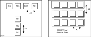
Second, do you know where I can find the numbering and coordinates of the MIMO virtual antenna array of AWR1843AOP? The antenna placement figure in the datasheet does not clear how each virtual array element is numbered  
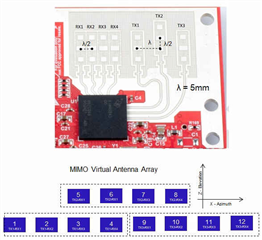
I am looking for something like this for AWR1843AOP:
Thank you for your attention to my inquiry.

Kind regards,

Jiawei

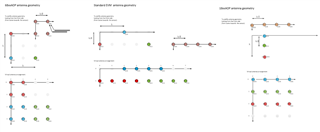
  • I have actually found the AWR1843AOP's antenna geometry in file:///C:/ti/mmwave_sdk_03_06_00_00-LTS/packages/ti/datapath/dpc/dpu/aoa2dproc/docs/doxygen/html/index.html/
    which made me think the labeling of TX antennas in the 1843AOP datasheet is incorrect. 

    WIth that, I am still wondering how we could incorporate this geometry into the MRR demo code.

  • Hi,

    Let me check this internally with the team and get back an update for you.

    Thanks,

    Pradipta.

  • Hi,

    The MMR demo supports two modes 

    1) The MRR mode (Beamforming) : All 3 Tx enabled at the same time

    2) MIMO (USRR) : One TX enabled at a time.

    It is possible to run the Beamforming mode on AOP (you will need to rebuild the demo for AOP board, we can provide assistance on this)

    If you are looking for the MIMO mode then it will not be possible as the software updates will be very complex before rebuilding it for AOP device. So what is the use case you are looking for ?

    Thanks,

    Pradipta.

  • Hi Pradipta,

    Thank you for the response. However, you didn't answer my questions directly. My first question asked how the demo code incorporated the antenna geometry configuration. Second, how is the virtual antenna array is numbered? 

    We are working on a close-range (0.2m to 2m) multi-static-object detection problem. We would want to obtain the elevation or z-axis information, which is why we would like to implement TDM MIMO. 

    Kind regards,

    Jiawei

  • Hi Jiawei,

    Please refer to the datasheet provided figure for virtual antenna numbers. So the top left will be TX1 and RX4. You can map the numbering on this basis.

    I will suggest you to go through one example of AWR1843BOOST and AWR1843AOP respectively, to understand the difference between the two implementations and how different antennas configuration affects the processing chain. Making the changes in the chain will help you to adapt your board to the required demos.

    Thanks,

    Pradipta.

  • Hi Pradipta,

    I don't mean to be rude, but I think you gave cheap answers to my questions after spending 6 days discussing them internally while still not answering them directly.

    I asked how the virtual antenna array is numbered, as shown in the other figure I initially attached, which the 1843AOP datasheet didn't provide. 

    Second, if we want to apply the USRR mode of the MRR demo to AWR1843AOP,  I believe we would have to change the angle estimation part as far as the post-processing is concerned.  Could you please show me where the antenna geometry information is encoded in the MRR demo code so I can change it for the AOP?  

    Please have someone with expertise in this step in to answer my questions. 

    Kind regards,

    Jiawei