This thread has been locked.

If you have a related question, please click the "Ask a related question" button in the top right corner. The newly created question will be automatically linked to this question.

DCA1000EVM: High Phase noise

Part Number: DCA1000EVM
Other Parts Discussed in Thread: AWR1642BOOST

Hi Team,

Can you help with solving the customer issue regarding phase noise? The customer browsed the forum but was unable to find a solution.

They are trying to obtain vital signs with raw data using the AWR1642BOOST + DCA1000EVM. They can detect chest correctly in the range fft. However, the phase obtained from fft complex from single chirp each successive frame has very high noise and it shows no signs of vital sign. hey think thata there is some kind of noise compensation at the steps of capturing data.

What they did was to first obtain the adc data bin file > process the bin file and obtain the range bin of target > obtain the complex data per frame to get phase using arc tangent. Also wanted to ask is if there is there is option to make the radar fmicw (i = interupted) in mmwavestudio so there are less reflections?

I have attached the Figures and Raw data below:

4338.Files.zip

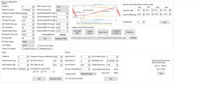
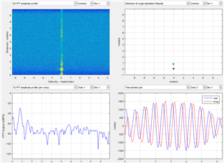
In the above, The customer simple parameters for recording fast 10s data. Parameters >>> Frames = 250, chirp = 3, adc = 128 and just use rx = 1. The circle dot figures are of the complex points they obtain from each rangefft. So 250 frames and we chose the second chirp as they saw some reference work that it provides better results. Also they find the range bin for most cases max peak is 10-13. basically they use the bin in this range and replace it with 10 incase it some random number like 2 because of their chest target is 10-13.

The attached two figures of the complex plot shows just random data. also have the phase displacement signal. This is obtained by arc tangent demodulation on the complex values and taking the difference for each successive point. This plot shows that there is large noise and sudden outliers.

The first observation that came to my mind is that It may be a problem with the parsing of data so I pointed them to this thread however, it does not solve the issue.

Can you please help?

Thanks in advance.

Regards,

Marvin

  • Hi,

    Unfortunately our support team has limited knowledge with this application.

    It seems that the customer is implementing a vital signs detection algorithm in matlab.

    There is a lab that can be used as reference.

    mmwave_automotive_toolbox_3_6_0__all\mmwave_automotive_toolbox_3_6_0\labs\incabinsensing\driver_vital_signs

    Unfortunately we don't have a Matlab model available

    Also, there have been threads related to vital signs detection

    Please use google site search as follows

    site e2e.ti.com vital signs

    Thank you

    Cesar

  • Hi,

    If there is high magnitude and phase shift in the adc data bin file obtained from the mmwavestudio, what can be done to improve this raw data? A high shift in the raw data (iq channels) means that IQ complex point used for phase will have high error due to the large shifts in raw data iq channels. I also checked the mentioned thread, but still the reuslts are similar. Is there any other solution to improve the raw data from the mmwavestudio setting or dca1000evm. I have tested this with multiple radar chips so the issue has to be related the the raw data extraction process before vital sign processing, which leaves the steps of mmwavestudio and dca1000evm.

  • Hi,

    What is the configuration used to collect the raw data? Do you have a LUA script?

    Thank you

    Cesar

  • Hi Cesar,

    Below is the configuration from the customer:

    Please let me know if you need more information.

    Regards,

    Marvin

  • Hi,

    Could the customer also provide snapshots of other mmwave studio tabs that were modified

    • Connection
    • Static Config
    • Data Config

    I recommend the customer creates a LUA script that will include the configuration. Similar to the following. This should save a lot of time

    https://e2e.ti.com/support/sensors-group/sensors/f/sensors-forum/1112328/dca1000evm-false-return-in-data-dca1000evm-awr1843boost/4122568?tisearch=e2e-sitesearch&keymatch=frameconfig#4122568

    Thank you

    Cesar

  • Hi Cesar,

    The customer is facing an issue posting a reply. He has provided the screenshots for all the tabs that were changed, which are attached below. He mentioned that he is inexperienced in generating the lua script file, so only the screenshots are provided.

    GM: Constructor
    GM: Fri Oct 07 09:59:55 2022
    RSTD.Transmit("/Settings")
    [09:59:55]  
    [09:59:55]  ### Running Startup script: "C:\ti\mmwave_studio_02_01_01_00\mmWaveStudio\Scripts\Startup.lua" ###
    [09:59:55]  RSTD.SetAndTransmit ("/Settings/Scripter/Display DateTime" , "1")
    [09:59:55]  RSTD.SetAndTransmit ("/Settings/Scripter/DateTime Format" , "HH:mm:ss")
    [09:59:55]  Scripter ignored: Attempt to UnBuild() again or before Build.
    [09:59:55]  RSTD.SetVar ("/Settings/Clients/Client 0/Dll" , "C:\\ti\\mmwave_studio_02_01_01_00\\mmWaveStudio\\Clients\\\\LabClient.dll")
    [09:59:55]  RSTD.SetVar ("/Settings/Clients/Client 0/Use" , "TRUE")
    [09:59:55]  RSTD.SetVar ("/Settings/Clients/Client 1/Use" , "FALSE")
    [09:59:55]  RSTD.SetVar ("/Settings/Clients/Client 2/Use" , "FALSE")
    [09:59:55]  RSTD.SetVar ("/Settings/Clients/Client 3/Use" , "FALSE")
    [09:59:55]  RSTD.SetVar ("/Settings/Clients/Client 4/Use" , "FALSE")
    [09:59:55]  RSTD.SetVar ("/Settings/AL Client/AL Dll" , "C:\\ti\\mmwave_studio_02_01_01_00\\mmWaveStudio\\RunTime\\SAL.dll")
    [09:59:55]  RSTD.SetVar ("/Settings/Clients/Client 0/GuiDll" , "")
    [09:59:55]  RSTD.SetVar ("/Settings/AutoUpdate/Enabled" , "TRUE")
    [09:59:55]  RSTD.SetVar ("/Settings/AutoUpdate/Interval" , "1")
    [09:59:55]  RSTD.SetVar ("/Settings/Monitors/UpdateDisplay" , "TRUE")
    [09:59:55]  RSTD.SetVar ("/Settings/Monitors/OneClickStart" , "TRUE")
    [09:59:55]  RSTD.SetVar ("/Settings/Automation/Automation Mode" , "false")
    [09:59:55]  RSTD.Transmit("/")
    [09:59:55]  RSTD.SaveSettings(): Settings saved to "C:\Users\Lovedeep\AppData\Roaming\RSTD\config.xml"
    [09:59:55]  RSTD.Build()
    [09:59:55]  RSTD.SaveSettings(): Settings saved to "C:\Users\Lovedeep\AppData\Roaming\RSTD\config.xml"
    [09:59:55]  RSTD.Transmit("/")
    [09:59:55]  RSTD.AL_Build()
    [09:59:55]  RSTD.AL_LoadXml()
    [09:59:55]  RSTD.Transmit("/")
    [09:59:55]  RSTD.AL_Init()
    [09:59:55]  RSTD.Clients_Build()
    [09:59:55]  GM: Init
    [09:59:56]  GM: Loaded 'C:\ti\mmwave_studio_02_01_01_00\mmWaveStudio\Clients\\LabClient.dll'
    [09:59:56]  GM: 1 Guest (s) init
    [09:59:56]  GM: 1 Module(s) init
    [09:59:56]  GM: 2 Tab   (s) init
    [09:59:56]  RSTD.Client_LoadXml()
    [09:59:56]  [RadarAPI]: ar1.selectRadarMode(0)
    [09:59:56]  [RadarAPI]: Status: Passed
    [09:59:56]  Matlab Runtime Engine is installed
    [09:59:56]  [RadarAPI]: Starting Matlab Engine..
    [10:00:13]  [RadarAPI]: Matlab Engine Started!
    [10:00:15]  [RadarAPI]: ar1.selectCascadeMode(0)
    [10:00:15]  [RadarAPI]: Status: Passed
    [10:00:15]  [RadarAPI]: ar1.LoadSettings('C:\Users\Lovedeep\AppData\Roaming\RSTD\ar1gui.ini')
    [10:00:15]  TESTING = false
    [10:00:15]  RstdNet: Port 2777: Listening..
    [10:00:15]  
    [10:00:15]  ***Script completed successfully.***
    [10:01:13]  [RadarAPI]: Opening Gpio Control Port()
    [10:01:13]  [RadarAPI]: Status: Passed
    [10:01:13]  [RadarAPI]: Opening Board Control Port()
    [10:01:13]  [RadarAPI]: Status: Passed
    [10:01:14]  [RadarAPI]: ar1.FullReset()
    [10:01:14]  [RadarAPI]: Status: Passed
    [10:01:15]  [RadarAPI]: Closing Board Control Port()
    [10:01:15]  [RadarAPI]: Status: Passed
    [10:01:15]  [RadarAPI]: Closing Gpio Control Port()
    [10:01:15]  [RadarAPI]: Status: Passed
    [10:01:15]  [RadarAPI]: ar1.SOPControl(2)
    [10:01:15]  [RadarAPI]: Status: Passed
    [10:02:00]  [RadarAPI]: ar1.Connect(3,921600,1000)
    [10:02:02]  [RadarAPI]: Warning: Connected with baudrate 115200
    [10:02:03]  [RadarAPI]: Warning: Disconnected existing BaudRate
    [10:02:04]  [RadarAPI]: Warning: Trying to connect with baudrate 921600
    [10:02:05]  [RadarAPI]: ar1.Calling_IsConnected()
    [10:02:06]  [RadarAPI]: ar1.SelectChipVersion("AR1642")
    [10:02:06]  [RadarAPI]: Status: Passed
    [10:02:06]  [RadarAPI]: ar1.SelectChipVersion("AR1642")
    [10:02:06]  [RadarAPI]: Status: Passed
    [10:02:06]  [RadarAPI]: ar1.deviceVariantSelection("XWR1642")
    [10:02:06]  [RadarAPI]: Status: Passed
    [10:02:06]  [RadarAPI]: ar1.frequencyBandSelection("77G")
    [10:02:06]  [RadarAPI]: ar1.SelectChipVersion("XWR1642")
    [10:02:06]  [RadarAPI]: Status: Passed
    [10:02:06]  Device Status : XWR1642/ASIL-B/SOP:2/ES:2
    [10:02:06]  [RadarAPI]: ar1.SaveSettings('C:\Users\Lovedeep\AppData\Roaming\RSTD\ar1gui.ini')
    [10:02:13]  [RadarAPI]: ar1.DownloadBSSFw("C:\\ti\\mmwave_studio_02_01_01_00\\rf_eval_firmware\\radarss\\xwr16xx_radarss.bin")
    [10:02:13]  [RadarAPI]: Downloading BSS Patch RPRC Binary..
    [10:02:15]  [RadarAPI]: ar1.GetBSSFwVersion()
    [10:02:15]  [RadarAPI]: BSSFwVersion:(02.00.00.01 (05/10/17))
    [10:02:16]  [RadarAPI]: ar1.GetBSSPatchFwVersion()
    [10:02:16]  [RadarAPI]: BSSPatchFwVersion:(01.02.05.02 (30/04/19))
    [10:02:17]  [RadarAPI]: ar1.DownloadMSSFw("C:\\ti\\mmwave_studio_02_01_01_00\\rf_eval_firmware\\masterss\\xwr16xx_masterss.bin")
    [10:02:17]  [RadarAPI]: Downloading MSS RPRC Binary..
    [10:02:20]  [RadarAPI]: ar1.GetMSSFwVersion()
    [10:02:20]  [RadarAPI]: MSSFwVersion:(01.02.05.02 (16/07/19))
    [10:02:22]  [RadarAPI]: ar1.PowerOn(0, 1000, 0, 0)
    [10:02:22]  [RadarAPI]: Status: Passed
    [10:02:22]  MSS power up done async event received!
    [10:02:26]  [RadarAPI]: ar1.SelectChipVersion("AR1642")
    [10:02:26]  [RadarAPI]: Status: Passed
    [10:02:26]  [RadarAPI]: ar1.SelectChipVersion("XWR1642")
    [10:02:26]  [RadarAPI]: Status: Passed
    [10:02:26]  Device Status : XWR1642/ASIL-B/SOP:2/ES:2
    [10:02:26]  [RadarAPI]: ar1.RfEnable()
    [10:02:26]  BSS power up done async event received!
    [10:02:26]  [RadarAPI]: Status: Passed
    [10:02:27]  [RadarAPI]: ar1.GetMSSFwVersion()
    [10:02:27]  [RadarAPI]: MSSFwVersion:(01.02.05.02 (16/07/19))
    [10:02:27]  [RadarAPI]: ar1.GetBSSFwVersion()
    [10:02:27]  [RadarAPI]: BSSFwVersion:(02.00.00.01 (05/10/17))
    [10:02:28]  [RadarAPI]: ar1.GetBSSPatchFwVersion()
    [10:02:28]  [RadarAPI]: BSSPatchFwVersion:(01.02.05.02 (30/04/19))
    [10:04:10]  [RadarAPI]: ar1.ChanNAdcConfig(1, 1, 0, 1, 1, 1, 1, 2, 1, 0)
    [10:04:10]  [RadarAPI]: Status: Passed
    [10:04:13]  [RadarAPI]: ar1.LPModConfig(0, 0)
    [10:04:13]  [RadarAPI]: Status: Failed, Error Type: REGULAR ADC MODE NOT SUPPORTED IN 5 MHz PART VARIANT DEVICE
    [10:04:15]  [RadarAPI]: ar1.RfInit()
    [10:04:15]  RF Init async event received!
    [10:04:15]  [RadarAPI]: Status: Passed
    [10:04:15]  [RadarAPI]: Time stamp, Temperture: 108860,37; APLL Status, Update: 1, 0; SynthVCO1 Status, Update: 1, 1; SynthVCO2 Status, Update: 1, 1; LODist Status, Update: 1, 1; RxADCDC Status, Update: 1, 1; HPFcutoff Status, Update: 1, 1; LPFcutoff Status, Update: 1, 1; PeakDetector Status, Update: 1, 1; TxPower Status, Update: 1, 1; RxGain Status, Update: 1, 1; TxPhase Status, Update: 0, 0; RxIQMM Status, Update: 1, 1; 
    [10:05:42]  [RadarAPI]: ar1.DataPathConfig(513, 1216644097, 0)
    [10:05:42]  [RadarAPI]: Status: Passed
    [10:05:43]  [RadarAPI]: ar1.LvdsClkConfig(1, 1)
    [10:05:43]  [RadarAPI]: Status: Passed
    [10:05:48]  [RadarAPI]: ar1.LVDSLaneConfig(0, 1, 1, 0, 0, 1, 0, 0)
    [10:05:48]  [RadarAPI]: Status: Passed
    [10:06:30]  [RadarAPI]: ar1.ProfileConfig(0, 77, 100, 6, 60, 0, 0, 0, 0, 0, 0, 29.982, 0, 64, 2500, 0, 0, 48)
    [10:06:30]  [RadarAPI]: Status: Passed
    [10:06:41]  [RadarAPI]: ar1.ChirpConfig(0, 0, 0, 0, 0, 0, 0, 1, 1, 0)
    [10:06:41]  [RadarAPI]: Status: Passed
    [10:07:07]  Test Source Already Disabled...!!!
    [10:07:07]  [RadarAPI]: ar1.DisableTestSource(0)
    [10:07:07]  [RadarAPI]: Status: Passed
    [10:07:07]  [RadarAPI]: ar1.FrameConfig(0, 0, 250, 2, 40, 0, 0, 1)
    [10:07:07]  [RadarAPI]: Status: Passed
    [10:08:23]  [RadarAPI]: ar1.GetCaptureCardDllVersion()
    [10:08:23]  [RadarAPI]: Sending dll_version command to DCA1000
    [10:08:23]  [RadarAPI]: 
    [10:08:23]  DLL Version : 1.0
    [10:08:23]  [RadarAPI]: ar1.SelectCaptureDevice("DCA1000")
    [10:08:23]  [RadarAPI]: Status: Passed
    [10:08:25]  [RadarAPI]: ar1.CaptureCardConfig_EthInit("192.168.33.30", "192.168.33.180", "12:34:56:78:90:12", 4096, 4098)
    [10:08:25]  [RadarAPI]: ar1.CaptureCardConfig_Mode(1, 2, 1, 2, 3, 30)
    [10:08:25]  [RadarAPI]: ar1.CaptureCardConfig_PacketDelay(25)
    [10:08:25]  [RadarAPI]: Sending fpga command to DCA1000
    [10:08:25]  [RadarAPI]: 
    [10:08:25]  FPGA Configuration command : Success
    [10:08:25]  [RadarAPI]: Sending record command to DCA1000
    [10:08:25]  [RadarAPI]: 
    [10:08:25]  Configure Record command : Success
    [10:08:25]  [RadarAPI]: ar1.GetCaptureCardFPGAVersion()
    [10:08:25]  [RadarAPI]: Sending fpga_version command to DCA1000
    [10:08:25]  [RadarAPI]: 
    [10:08:25]  
    [10:08:25]  FPGA Version : 2.8 [Record]
    [10:08:25]  
    [10:08:49]  [RadarAPI]: ar1.CaptureCardConfig_StartRecord("C:\\ti\\mmwave_studio_02_01_01_00\\mmWaveStudio\\PostProc\\adc_data.bin", 1)
    [10:08:49]  [RadarAPI]: Sending start_record command to DCA1000
    [10:08:56]  [RadarAPI]: ar1.StartFrame()
    [10:08:56]  [RadarAPI]: Status: Passed
    [10:08:56]  Frame start async event received!
    [10:09:06]  [RadarAPI]: Frame Ended
    [10:09:08]  [RadarAPI]: 
    [10:09:08]  Frame End async event received!
    [10:09:08]  [RadarAPI]: 
    [10:09:08]  Start Record command : Success
    [10:09:08]  
    [10:09:08]  Record is completed
    [10:09:08]  
    [10:09:08]  Record stop is done successfully
    [10:09:17]  [RadarAPI]: ar1.StartMatlabPostProc("C:\\ti\\mmwave_studio_02_01_01_00\\mmWaveStudio\\PostProc\\adc_data.bin")
    [10:09:17]  [RadarAPI]: No of files Captured: 1, Total no of frames for each device : 250
    [10:12:52]  LuaSave("C:/Users/Lovedeep/Desktop/data.lua")LuaSave("C:/Users/Lovedeep/Desktop/lua.txt")RSTD.ShowLogFile()
    

    Regards,

    Danilo

  • Hi Team, 

    Here is additional information: Below is a paper that does the exact same experiment. The Iq plot can be seen in fig 4.

    Remote_Monitoring_of_Human_Vital_Signs_Using_mm-Wave_FMCW_Radar (1).pdf

    Please let me know if you need more information.

    Regards,

    Marvin

  • Hi,

       Can you please confirm if the customer has gone through the TIREX release in the link for the chain implementation: https://dev.ti.com/tirex/explore/node?node=A__ADZIzSoqYpsJx3iqoalh2A__com.ti.mmwave_automotive_toolbox__AocYeEd__LATEST ? Also, there are references for the same in: https://dev.ti.com/tirex/explore/node?node=A__AEF-xSY.v4TPVEesooUlmw__com.ti.mmwave_industrial_toolbox__VLyFKFf__LATEST ?

    Thanks and Regards,

    Akshay

  • Hi Akshay,

    Yes, they have gone through the links you provided. Also, the customer is requesting if we could focus on the "Raw adc data" part, as we suspect that the issue might be in the parsing of data (or maybe not? please let us know).

    The customer is also waiting for the new DCA1000 to try this again.

    Thanks and regards,

    Marvin

  • Hi, Marvin:

    I would suggest to take the raw data capture with static scene first. i.e., no chest movement or human, just a corner reflector to understand the stable of phase.  If the phase change on a static corner reflector is within the expectation, then we know that the device, capture system are all good.   

    Best,

    Zigang

  • Hi Zigang,

    Here is the customer response:

    "I tried something similar already but working on checking this again. I wanted to ask why there is large error even for brand new devices. I have been able to get much better results for same experiment last year but now there is this erroneous data. Even the reference paper you can see the results of displacement from vibrations using 1tx 1 rtx pair is much cleaner. The complex points of peak range fft are in an arc showing vibration effect but here we are getting error with complex points from peak range fft being largely shifted and resulting in these points being being at shifted locations and not getting that arc affect. Having this done before and also the work like the reference paper which is why I was hoping there is some setting with mmWave studio that I am missing because We are not able to results even with brand new devices."

    I hope you can help further.

    Regards,

    Marvin

  • Hi, Marvin:

    I checked their configuration file, and run through the rampTimingCalculator tab inside the mmwave Studio GUI.   I think they can use a little bit longer total ramp time and longer ADC start time.  Please follow the figure below with orange box.   

    Best,

    Zigang

  • Hi Team, 

    Thank you for waiting. The customer tried your suggestions however the results are still the same.

    The results still have that same error discussed before and they are not sure why since they have gotten good results before.

    There are other research works as similar to what I have shared before with figures that get good results. For some reason, They can't get those results again.

    Do you have any other suggestion on how they can proceed?

    Regards,

    Marvin

  • Hi, Marvin:

    Please ask the customer to provide the heatmap plot in postProc generated in mmWave studio with static target to see whether range-Doppler heatmap looks normal.  I won't be able to help with non-static target results. 

    Best,

    Zigang

  • Hi Zigang,

    Thank you for your continuous support. Here is the heatmap images:

    The customer took the capture at target being less than 1m.

    I hope this helps. Let me know if you need more information.

    Regards,

    Marvin

  • HI, Marvin:

    Thank you!  What are these two figures?  Does the two figures above shows the first and second chirp of the capture?  ADC data does show big variation. 

    Best,

    Zigang

  • Hi Zigang,

    What are these two figures? 

    Apologies for this. The figures provided were from different captures, frames and chirps.

    Please see the new attached images below. These new figures are named as f = frame and c = chirp number (ie. f1c1 = frame 1 and chirp 1).

    The customer added frame1's chirp 1-3 so you can check if it's correct. Coming to the phase extraction, they only need a single chirp from each frame. So an example for the data would be f1c2, f2c2 and f3c2 (getting chirp 2 from every single frame), which is also provided to see if plots are ideal. Please let me know if more information is required.

    8015.attachments.zip

    Let me know if you need more information.

    Regards

    Marvin

  • Hi, Marvin:

    From the figure, it shows the signal variation within f1 is very small (f1c1, f1c2, f1c3).  However, the variation between frames are very observable (f1c2, f2c2, f3c2).  

    1) Can you confirm that the results are captured with static target?

    2) Can you send me the chirp configuration they are using for me to review?

    Best,

    Zigang

  • In addition, if the answer is Yes for static target,  Please ask them to send me the binary data as well.

    Best,

    Zigang

  • Hi Zigang,

    The results were taken with the customer sitting on a chair still in front of radar. Is that ok? or should  it be an empty chair? The measurement of the chest will have phase variation.

  • Hi, Marvin:

    The phase will change with a person sitting in a chair.  So I can not analyze whether it is too much or too little.   I can only help to analyze whether the phase of capture is stable when the target is static.   To help rule out any configuration or capture issue.  

    Best,

    Zigang 

  • Hi Zigang,

    Thank you.

    Attached here is the results of a static square object sitting in front of radar at roughly 1m. The screenshot of the setting and config file is also attached including a static 128 and 3 chirp bin file. The customer's ideal setting is 3 because they only need to pick 1 chirp per frame added a 128 so the range doppler can also be checked if required. The chirp number is the only difference between the two bin files.

    binaries.zip

    Let me know if you need more informatoin

    Regards,

    Marvin

  • Hi, Marvin:

    Here is the phase change over 128 frames for 3 chirp bin file. 

    The phase error cross 128 frames is about 0.06rads, which is about 3.4degree.   The phase variation looks small to me. 

    Best,

    Zigang

  • And here also attached the MATLAB script that parse the binary file and plot the phase variation. 

    Best,

    Ziganghttps://e2e.ti.com/cfs-file/__key/communityserver-discussions-components-files/1023/RawAdcDataProc_5F00_complex1x_5F00_phaseAnalysis.m

  • Hi Zigang,

    The customer saw the message and wanted to ask:

    "Thank you for checking the static case. The static object capture in this case has very low error. If we plot the peak values per frame, there would be no relation. However, for a case with varying phase, it should result in an arc/circular shape, but it cannot be differentiated between a static or non static case. I have attached a figure I previously shared of the complex points. Also, I am sharing a few figures of the example work paper by an author also here at TI. I have attached the range slow time map figures which show that vibrational activity can be seen in the range of the peak over time (frames). My question is why the snr is very low in which we cannot differentiate between a static or nonstatic(vibration case) slow time vs range. Also, the peak complex values I mentioned above are also of random shape for static and nonstatic case that cannot be differentiated. It is some sort of snr issue because the plotting the frame vs range should show us some sort of visible distance, but the low snr makes it seem like both are static cases and no vibrational object in front. Thanks"
    Let me know if you need more information.
     
    Regards,
    Marvin
  • HI, Marvin:

    For this thread, the customer thinks the DCA1000 data capture has issues.  I have proved through their static capture, that there is no problem with device or DCA1000 data capture.  Now it is more of a problem with vital sign signal processing. 

    I would recommend to close this thread and start a new thread with the right title and content.

    Best,

    Zigang