This thread has been locked.
If you have a related question, please click the "Ask a related question" button in the top right corner. The newly created question will be automatically linked to this question.
Hi, Support Team
We use TI TMP75AIDGKR for temperature sensor source, Need your help to clarify some question:
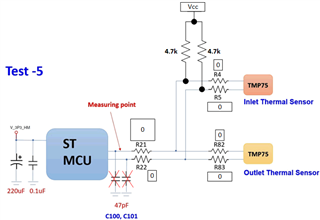
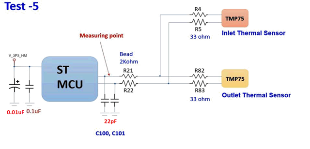
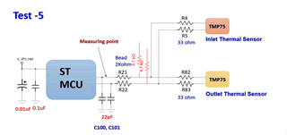
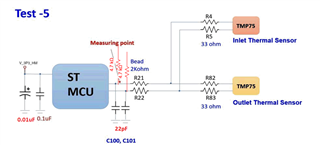
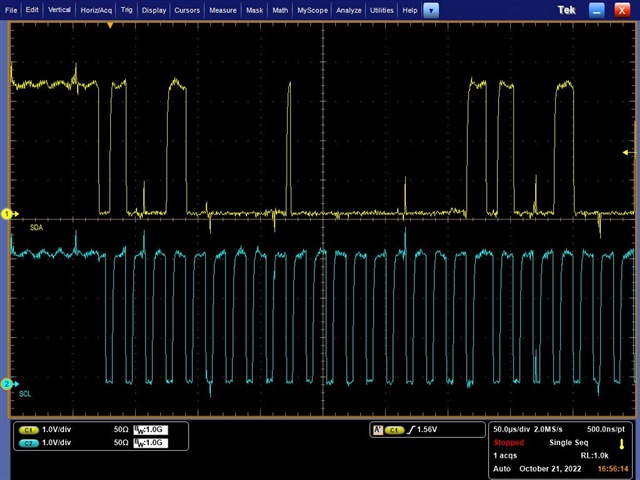
Heater Module is use for the system that will be in the low ambient temperature,and when the system shut down, heater will start to heat the system.There are two sensors in module. One for detect ambient temp(Inlet sensor), another for detect the heat air flow temp(outlet sensor).There is the question, when heater on(below ambient temp -3C), I2C signal is going to be interfered and turn fail.
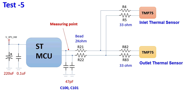
Q1. EE team find out the I2C signals have some noise(from another known power issue), and we added some capacitors to offset them, the waveform look better, but when we put UUT back to chamber,
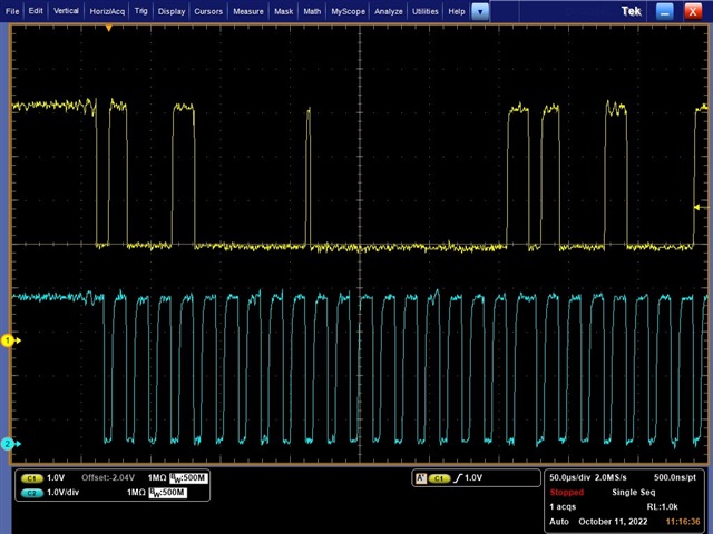
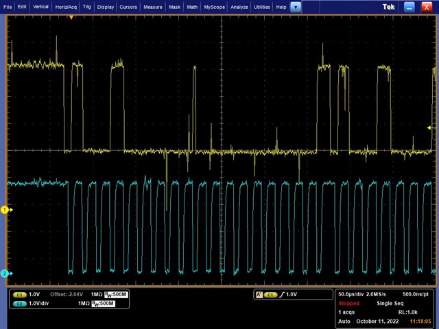
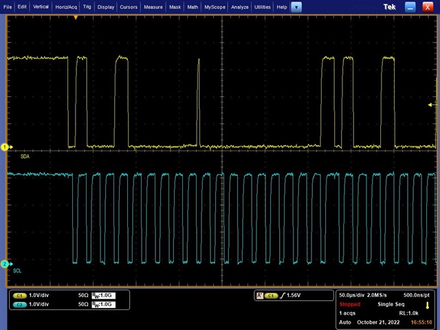
there still show fail. Attachment is for the I2C signals waveform and the log of I2C signal in room temperature and -3 degree C.
Is there recommendation solution for us?
Q2. Is there any know issues with reading temperatures below zero (55 degree C to -20 degree C for our operating temp.)?
Q3. For using I2C analyzer in chamber(-3 degree C), is there any recommendation for setting up the analyzer?
Q4. If we are going to measuring the I2C signals with an Oscilloscope when UUT is in chamber, is there any recommendation for setting up?
I2C signal before/after heat on:(See attached file: IMG_4415.JPG)(See attached file: IMG_4416.JPG) and added the test-5 solution(before/after heat on): (See attached file: IMG_4417.JPG)(See attached file: IMG_4418.JPG)
(See attached file: FAIL_-3C.csv)(See attached file: PASS_RoomTemp.csv)
IMG_4415:
IMG_4416:
IMG_4417:
IMG_4418:
If any suggestion, Please advise me.
Thanks,
Best regards,
Lawrence
Hi Lawrence,
Thank you for posting to the Sensing forum.
Can you please provide a scope shot of a failing I2C transaction? This will help us determine if the noise added by the heater is the cause of the failures.
Best regards,
Nicole
The allowable temperature range of this sensor is −40°C to +125°C. So, there should not be any issue with your mentioned range.
Hi, Nicole and Zain
will post soon, if client add 200pF cap to ground to reduce I2C bus noise, it`s make sense?
as i know (max, allowed capacitance on the i2c-bus is 400pF including wires, pin-capacitance etc...) it`s might only cause problems?
By the way about Q3 & Q4, have any suggestion?
if any, Please advise me.
Thanks,
Best regards,
Lawrence
I don't think the 200pF cap will create any problem. But there is a mixed opinion about this matter.
https://forum.arduino.cc/t/i2c-problem-sdl-high-and-sda-low/479136
https://www.microchip.com/forums/m456630.aspx
And I have less experience in oscilloscope operations. So, can't comment about Q3 & Q4.
Lawrence -
Please ensure first the customer changes their circuit as shown below, then retest.
if you are wanting to measure I2C traffic while the unit is in a chamber, more than likely you would want to keep the analyzer outside the chamber, and just run the wires from the DUT to the LSA through the side chamber opening. Same with o'scope probes, i would keep them outside the chamber as well.
Hi, Josh and Nicole
Thanks for the feedback, please see as attached.
We already added 3.3V pull up with 4.7k ohm on I2C path, FYI
Heater Module I2C_withcaps 20221103.xlsxHeater Module I2C_wihtout caps 20221102.xlsx
(See attached file: Heater Module I2C_withcaps 20221103.xlsx)(See attached file: Heater Module I2C_wihtout caps 20221102.xlsx)
if any suggestion, Please advise me.
Thanks,
Best regards,
Lawrence
Hi Lawrence,
Thank you for providing these extra details.
Did you also remove R4, R5, R21, R22, R82, R83? Additionally, in the passing .csv file there is a device with address 0x50. This is not a TMP75 address, can you please confirm what other devices are on the bus?
If possible please send the direct logic analyzer output file of a failing transaction, since the attached FAIL_-3C.csv output does not seem to be formatted correctly.
Best regards,
Nicole
Hi, Nicole
Did you also remove R4, R5, R21, R22, R82, R83? Additionally, in the passing .csv file there is a device with address 0x50. This is not a TMP75 address, can you please confirm what other devices are on the bus?
1.our client do not remove R4,R5,R22,R82,R83, it`s can help to filter noise.
2.0x50 is EEPROM address.
If possible please send the direct logic analyzer output file of a failing transaction, since the attached FAIL_-3C.csv output does not seem to be formatted correctly.
Please see as attached. Fail_1031.csv
BTW about I2C waveform as below, is good or have any concern?
2112.Heater Module I2C_withcaps 20221103.xlsx7167.Heater Module I2C_wihtout caps 20221102.xlsx
if any suggestion, Please advise me.
Thanks,
Best regards,
Lawrence
Hi Lawrence,
How are the 4.7 kΩ pull up resistors placed in the schematic? Layout #1 or #2? Please attach a full schematic if possible.
#1:
#2:
If they are placed according to #1 you are creating a voltage divider, and it's possible that SCL voltage is not reaching ground. This behavior would not be seen with the measuring point you are currently using. The TMP75 may still operate properly this way, but the added noise of the heater may be causing the I2C communication to become corrupted.
Best regards,
Nicole
Hi, Nicole
How are the 4.7 kΩ pull up resistors placed in the schematic? Layout #1 or #2?
is Layout#1
so change to Layout#2 is better right?
if any, Please advise me.
Thanks,
Best regards,
Lawrence
Hi Lawrence,
Yes, it appears that the pull-up resistors are placed according to Layout #1 in the attached schematic. I would recommend changing to Layout #2 and seeing if that fixes the I2C communication problem.
Best regards,
Nicole