This thread has been locked.

If you have a related question, please click the "Ask a related question" button in the top right corner. The newly created question will be automatically linked to this question.

IWR1843: Transimit the FMCW signal at very high speed

Part Number: IWR1843

Hi,

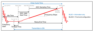
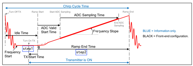
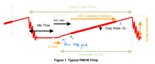
If I just need send the FMCW signal and don't need recevie the reflect signal and any sequent signal processing. In the following figure, it means we just need turn on the TX, and don't need the ramp time any more. Hence, we can send the FMCW signal at very high speed.

Am I right? How can I achieve it? Thanks.

  • Hi Jun,

    Please see our sensing estimator tool to get a feel for how these parameters impact the ability of the FMCW to sense motion and static objects. 

    You will see the transmitter is on during the ramp end time. This is the time that the FMCW signal is sent. You can modify the length of the ramp end time.

    What is your application with the FMCW? Do you have another sensor receiving these signals?

    Thank you,

    Angie

  • I want to use another sensor to recieve the signal. If the  ADC sampling time of the signla is t, then I want to let it be sent twice during the time t to make sure it can be recieved. But it is impossible if the ramp end time exists.

    Is there a method to send the FMCW signal and skip the ramp end time? Thanks.

  • Hi,

    I think you would want to instead reduce ramp end time to as small as it can be. Ramp end time = adc valid start time + adc sampling time + extra ramp end time. To ensure there is no extra time you would instead just set your ramp end time equal to adc valid start time + adc sampling time + a small buffer. 

    Please see this app note for more information.

    Thank you,

    Angie

  • Hi,

    The point is that in order to let the signal to be recieved by another sensor, these two sensor should produce the same FMCW signal. As I described, it is impossible to let the speed of send 2 time faster than the speed of recieve if we cannot omit the ramp end time of the reciever sensor. 

    I think IWR1843 should support the function of just send the FMCW signal (and omit the rest part) since it is one step of the whole chirp circle, it may be related to BSS. Could give me some information? Or doesn't any Ti's other products support this function?  Thanks.

  • HI, Jun:

    I do not understand what do you mean by "omit the ramp end time", do you mean you want to send a continuous waveform (CW) ?   In that case, you can send a continuous signal with constant RF frequency (the slope is zero).    If you want an non-zero slope signal, then your chirp will have to stop once it reach the maximum RF bandwidth (around 4G), which lead to a ramp structure.   

    In addition, please explain what you are trying to achieve here.  We can not really help without understanding your goal.  

    Best,

    Zigang

  • Hi zigang,

    My goal is to let one radar send the FMCW signal to another radar.

    In the normal one radar scenario, in one chirp circle, the radar performs following steps:

    1) Turn on the Tx and send the FMCW signal (TX start time)

    2) ADC valid time + ADC sampling time ( wait for recieving FMCW singals)

    3) Idle time for IF signal processing

    My two radars scenrio want to split the three steps into: the sender radar executes 1), and the reciever radar execute 2) 3).

    Firstly, the two radars will produce the same FMCW signal for the correct mix. For the reciever radar, I think it's just need turn off the TX to skip the step 1). For the sender radar, in order to let the signal to be recieved, it need to to sent as the speed of >2/ADC sampling time, so I asked if it supports skipping step 2) 3) and only execute 1). I think it can be realized in theory.

    Thanks.

  • Hi Jun,

    The ramp is when the signal is being sent. The signal being transmitted is set to ramp from a start frequency (like 60GHz) and ramp to an end frequency (like 64GHz, for a 4GHz bandwdith). The time has to be long enough for the signal to complete it's ramp, this is the ADC valid time + ADC Sampling Time. Even if you are not using the recievers this time is still needed for the signal to be sent. 

    Therefore I think you would be limiting your ramp end time to be equal to ADC valid start time + ADC sampling time in theory (in actuality you maybe need a few microseconds of buffer added to this). You would limit your idle time to it's absolute minimum and then make your frame time as the number of chirps * (ramp end time + idle time) to make sure it is at it's absolute minimum as well. 

    Thanks,

    Angie

  • “The ramp is when the signal is being sent. The signal being transmitted is set to ramp from a start frequency (like 60GHz) and ramp to an end frequency (like 64GHz, for a 4GHz bandwdith). The time has to be long enough for the signal to complete it's ramp, this is the ADC valid time + ADC Sampling Time. Even if you are not using the recievers this time is still needed for the signal to be sent. ”

    According to my understanding, the chirp period can be divided into two parts. One is time that the signal is sent. Another is the (ramp end) time that the sensor starts the (frequency-based) timer waiting for the reflected signal, and measure the flight time. Hence,  If we only need send the signal and don't care about recieved signals, the ramp end time can be removed.

  • Hi Jun,

    Yes, I agree, that "ramp end time" you are talking about is the excess ramp end time. We usually set ramp end time > ADC valid start time + ADC sampling time but in your case it would be virtually equal to the ADC Valid Start Time + ADC Sampling Time to remove that excess time.

    Thanks,

    Angie

  • HI, Jun:

    It is not correct that the ramp time can be divided into the two parts you described.  For example, the propagation delay of 10m target is about 66ns.  But the chirp is usually in ms.   So, the chirp transfer and receive is at the same time with very short delay.   You can check the figure below to understand its relative relationship between transmit signal and received signal.   The figure comes from the app notes at www.ti.com/.../swra662a.pdf

    So, for the TX signal from one device to be detected at the other device, the two chirp timing has to be really close, and it will be really hard if the two devices is not synchronized in some way. 

    Best,

    Zigang

  • OK. Thanks for your suggestion.

  • "So, for the TX signal from one device to be detected at the other device, the two chirp timing has to be really close, and it will be really hard if the two devices is not synchronized in some way. "

    Yes, if the sender sensor has the ramp time, it's signal is hard to be located in the interval of ramp time of the receive sensor. That's the reason I am wondering if the ramp time can be removed in the sender sensor, in this way the signal can be transmitted with very high speed and can be detected by the receiver sensor.

    In conclusion, I have two questions:

    1) Q1: For a mmwave radar, if we only need to send FMCW signals and don't care about the reflected issue, does the ramp time can be removed in theory?

    I think the answer is YES. 

    2) Q2: Does Ti provide any interface to remove the ramp time and send FMCW signals in the defined speed or in continuous way? 

    Thanks.

  • HI, Jun:

    1) Q1: For a mmwave radar, if we only need to send FMCW signals and don't care about the reflected issue, does the ramp time can be removed in theory?

    2) Q2: Does Ti provide any interface to remove the ramp time and send FMCW signals in the defined speed or in continuous way? 

    I am not sure what do you mean by ramp time.  Do you want to switch to continuous wave (CW)?  then it has to be constant RF frequency.   Yes, we support continuous wave in the radar device, but not in SDK OOB demo code.  you can use the mmWave studio to send and receive CW signal.  You will need DCA1000 capture board. 

    Best,

    Zigang 

  • Please see the above annotated figure. In the step1, the FMCW signal is sent. In the step2, the sensor is waiting for the reflected signal.  So, if I only need send the signal and don't care about the receiving of reflected signals, then step2 can be removed.  Does Ti provide interfaces to do it?

    Thanks.

  • HI, Jun:

    Your understanding is wrong and the figure is not accurate either.  Please check Figure 1 in the following app notes  to understand better.  https://www.ti.com/lit/an/swra553a/swra553a.pdf

    From the figure, you can see that TX is on for the whole ramp time.  Again,  unless we send CW  (continuous wave, constant frequency, zero slope) signal, we will always have to have this chirping pattern. 

    Best,

    Zigang   

  • Hi,

    I think the distance measurement is actually a Time of Flight method. In one time point, the sensor send the signal, and start the timer and receive the reflected signal and record the flight time. The difference is that FMCW use the time-varing frequence to replace the timer, just like a frequence-based timer. In this way, the FMCW signal should be sent in a time point. In my understanding, the time point is the starting time of the slop, as annotated in the figure.

    Otherwise, if the sensor continouslly send the same FMCW signals during the whole ramp time, the flight time calculated by the freqeunce difference between the send signal and received signal doesn't have any meanings. 

    Is my understanding correct? Thanks.

  • HI, Jun:

    Your understanding is wrong, TX do sends signal during the entire ramp time.   The following figure shows two target at different distance will create a reflected signal with different delay (the red line and the green line).  And results in two different value of IF frequency (show in the lower figure).    

    Please go through the training to understand FMCW fundamentals.  I will not be able to explain better than these training video.   

    Best,

    Zigang

  • Hi, Zigang,

    Thanks for your great patience.

    Assume the time-varying frequency is represented by f(t) = f_start+t*slope, I figure out that TX will continuously transmit signal of frequency f(t) in the time t during the entire ramp time, where 0<=t<=ramp_time. Am I right this time?

    I have one more related question. What's the speed of TX transmission? In other words, What's the interval time of two continuous transmissions?


  • HI, Jun:

    You are right this time.   The interval time of two chirp is just the idle time, which is programmable, but has a minimum number you can check through rampTImeCalculator tap inside mmwave studio.    In addition, you have to program frame duration to have close to 100% of duty cycle if you want to minimize the idle between frames.

    Best,

    Zigang 

  • Great, Thanks.