This thread has been locked.

If you have a related question, please click the "Ask a related question" button in the top right corner. The newly created question will be automatically linked to this question.

LDC1614EVM: Design details of LDC1614 EVM

Part Number: LDC1614EVM
Other Parts Discussed in Thread: LDC1614, LDC1312, LDC1314DIAL-EVM, LDC0851, LDC0851EVM

Hello Team,

   we had purchased evaluation board of LDC1614EVM. we have tested its basic features as per user guide.

As per LDC_Tools-ext51 we tried to understanding the calculation for spiral inductor design,LDC1614 config tool.

To understand in detail is there any document which show detail calculations of all these parameters mentioned in excel for LDC1614 eval kit.

like e.g calculation of sensor capacitance, inductance, number of turns etc.

Regards,

Sayali

  • Hello Sayali,

    Thank you for posting to the sensing forum! We do have a couple of Precision Labs videos on the LDC Calculator Tool, here is the intro video: https://training.ti.com/introduction-ldc-calculator-tool

    Here is the video that specifically covers the spiral inductor designer portion of the LDC tool: https://training.ti.com/spiral-inductor-designer-and-skin-depth

    We also have a document that covers some other details on designing all types of inductors: https://www.ti.com/lit/an/snoa930c/snoa930c.pdf

    I hope this helps and let me know if you have any more questions!

    Best,

    Isaac

  • Hello Lara ,

        Thanks for quick reply.

          The link which you have shared , I have already gone through it .

    As I said we have LDC1614 evaluation kit, I want to just verified its parameters with all calculations shown on your video.

    eg. sensor capacitance selected is 390pf but other parameter I don't know . physically I can see no. of turns are 14 and it is two layer board but need verification on this.

    is there document or video which explain design parameter values of this eval kit .

    even I want to know resolution is has set for below snapshot from excel tool calculation. Hope you have understood what I required. 

    Regards,

    Sayali

  • Hello Lara,

      one more thing is it possible to check output of kit on oscilloscope , if yes then can you please tell me at which point I can monitor the waveform on oscilloscope.

    Regards,

    Sayali

  • Hello Sayali,

    I apologize for that, I had misunderstood your question. You can see more details for the LDC1614EVM in the LDC131x and LDC161x EVM User's Guide: https://www.ti.com/lit/ug/snou135a/snou135a.pdf

    This document contains schematics and layout of the board along with the sensor coils. You can view the number of turns on the sensor using the Top and Bottom layers. The board does has 4 layers but the middle two layers do not contain coil windings.

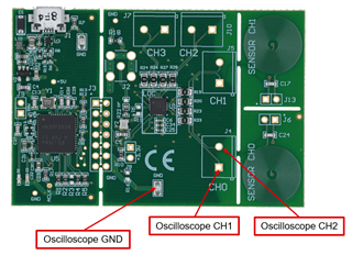
    If you are trying to monitor the raw sensor coil frequency and how its affect by targets, then you can probe coil1 using J5 or J13 and coil0 via J4 or J6. The device outputs the data digitally via I2C, so to view the sensors digital output data then it is best to use the GUI to view the digital representation.

    Best,

    Isaac

  • Hello Lara, 

     Thanks for details , I am getting variation in waveform but its like distorted .ideally how the waveform should look? do you have any snapshot of it.

    ultimately we want to use this chip for encoder development. is it possible to view output without connecting to GUI and not we are getting absolute output.

    is it possible to have incremental output like 512 ,1024 etc lines.

    Regards,

    Sayali

  • Hello Sayali,

    Make sure to probe the sensor from coil in reference to ground.

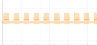
    Measuring the coil without a metal target the EVM signal looks like the following (excuse the noise on these probe): 

    When I add a metal target the signal more becomes attenuated the closer I get to the target:

    Since the data is output in a digital format only you would need a microcontroller to extract the raw data from the device and plot it for you, which is what the GUI handles for users. Unfortunately the device does not output any analog data, but you can always observe how the sensors are affected by targets by probing them manually, but just remember the device output is a digital representation of how the signal is manipulated.

    We do have firmware source code available that could help you write custom firmware to do what you need it to do: www.ti.com/.../snoc027

    Best,

    Isaac

  • Hello Isaac,

       Thank you for detail.

    one more query related to inductive sensor . I just went through below PDF of LDC1312 Incremental Encoder Knob

    https://www.ti.com/lit/ug/tidubg4/tidubg4.pdf?ts=1669613196957&ref_url=https%253A%252F%252Fwww.ti.com%252Fsitesearch%252Fen-us%252Fdocs%252Funiversalsearch.tsp%253FlangPref%253Den-US%2526searchTerm%253DLDC1312%2BIncremental%2BEncoder%2BKnob%2526nr%253D16.

    in this they have explain 32 incremental position , as per calculation 1024 lines is also possible. but to design 1024 sensor and target design will change.

    to have 1024 PPR , 4X256=1024

    target geometry will have 256 section each of 0.703125 degree ,separated by 0.703125degree

    is it possible to have to above section on PCB diameter of 15mm?

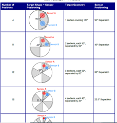
    one more query related to sensor design . In below snapshot for N number of positions they have used only 2 sensor with different in angle placement  as per calculation

    but for designing 32 position they have used 4 sensor placement, this is bit confusing. can you elaborate this . 

    Regards,

    Sayali

  • Hello Isaac,

       I tried to capture raw data but still not able to get it.

    I have attached one video in which LDC1614 evali kit, CRO ,copper tape and GUI is there.

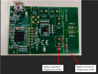
    I have connected LDC1614 eval kit to GUI and as I move copper tape over the sensor coil there is variation in inductance graph in GUI, at a same time I have connected CRO probe on eval kit as shown below and on CRO I am getting square wave but as as I move copper tape over sensor coil there is no any variation in signal on CRO 

    Regards,

    Sayali

  • Hello Sayali, 

    For connecting the LDC1614EVM to an oscilloscope, it looks like you have one side of the sensor channel connected to the GND of your scope probe in the video. The LDC1614 sensor waveform is a discontinuous sine wave so it would be best to measure each side of the sensor channel with a different oscilloscope channel and then take a differential by subtracting the two. For example, here is how the connection should be: 

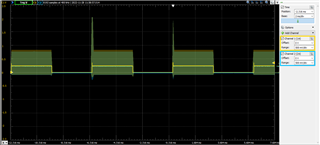
    Connecting this way, you will see something like this: 

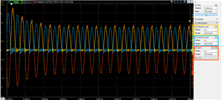
    Zooming in on the active channel window, you will see the sine wave:

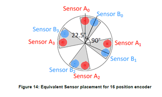
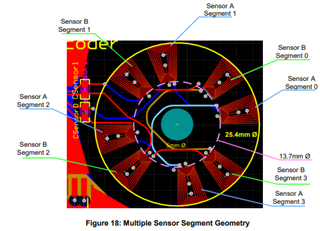
    In regards to the encoder question, figure 14 in the document you linked is showing all the locations where you will get equivalent data from the sensor placements. Increasing the number of channels here does not impact the number of positions detected. When the sensor design is implemented for the document, they are actually using multiple sensors in series to increase the inductance of the sensor. They utilize the equivalent placements to ensure that all sensor A segments are impacted the same way by the target but there are still only 2 sensors being used in the implementation with an 8 segment target to get 32 positions: 

    The challenge for implementing a 256 segment sensor in a 15mm space is the coil design. Your external arc length in a 15mm diameter circle would be less than 0.1mm which would not be enough space for a sensor. You would either need to increase the space for the coil or consider a different approach where you measure the angle similar to the LDC1314DIAL-EVM

    If neither of these are possible, an alternative approach to an encoder like this is to use a hall device as shown in the Using Hall-effect position sensors for rotary encoding video.

    Best Regards, 

    Justin Beigel

  • Hello Justine,

       Thank you for quick response . As per your suggestion by taking differential output I am able to get waveforms on CRO same what you share.

    can you suggest by increasing how much external arc length I will able to achieve 256 segments. I have gone through LDC1313 dial EVM but it gives absolute value and we want incremental output. we already have encoder design with other options which you suggested i.e hall sensor based, optical based ,MR based. we want to developed encoder with inductive sensor technology.

    can you some idea or design reference which will fill our requirement . we want to develop inductive encoder with incremental output with maximum 1024 PPR. If possible can we have call to discuss this.

    Regards,

    Sayali.

  • Hello Sayali, 

    The main concern with this is figuring out the smallest sensor you can build. If you were to put 2 turns in a sensor coil using a 4 mil trace width and spacing, then you would need at least 28mil (~0.7mm) spacing at the inner edge of the coil arc. For this, you would need the inner diameter of the sensing coil to be 114mm and the outside to be around 116mm. You would still likely need to have multiple coils in series as done in the app note. 

    Best Regards, 
    Justin Beigel

  • Hello Justin,

      Thank you for details , is it possible to use design of LDC1314DIAL-EVM where the design of PCB is quite simpler but the output is absolute one,  but with the help of controller I can change absolute to incremental one. If so please share some base coding example of converting absolute to incremental output.

    Regards,

    Sayali

  • Hello Sayali, 

    The 1º Dial Using the LDC1314 Inductance-to-Digital Converter Design Guide discusses the processing for determining the angle of the dial. From there, you could discretize it by segmenting the data based on the degree of rotation. We don't have any software examples to share of this but the steps are all outlines in the document. 

    Best Regards, 

    Justin Beigel

  • Hello Justin,

      Thanks for details and sorry for replying late, was on vacation.

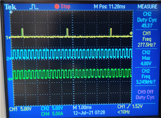
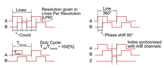
    currently whatever encoder we have it is two channel with quadrature output and one index pulse to indicate completion of one rotation. for reference refer below snapshot of encoder output. Its resolution is 12 PPR(pulse per revolution) / LPR(Line per revolution) i.e in one rotation it gives 12 high pulse . For us this is incremental output with 12PPR i.e high low pulse .Yellow is index pule, blue is channel A output and Green is channel B output. phase shift between ChA and CHB is 90 degree and duty cycle is 50%. second snapshot on right has side is just another reference from our catalog page.


     I went through your design guide of LDC0851 Incremental Rotary Encoder. working of LDC0851 is like comparator , it gives high low output . In LDC0851 Incremental Rotary Encoder with LDC0851 chip microcontroller is use to convert high low output into analog value from 1 to 32 positions. But LDC0851 gives only one output and we require two outputs for quadrature , for this we need to use two chip along with microcontroller.

    can you share some in details coding /documents for conversion of LDC output into required format using microcontroller and even we what to know back end coding of this " LDC0851 Incremental Rotary Encoder" which will help us for design.

    we went through this design also  LDC1312 Incremental Encoder Knob, as per name it is incremental output but our incremental is just high low pulse with index pulse. In this design LDC1312 gives digital output and microcontroller process into required format of incremental output.

    can you share coding details of this kit also like converting LDC output into incremental .

    we want to develop encoder without GUI , it should work independently . we will place the encoder on motor and as motor rotates encoder will give output as shown above . we don't output in seven segment which will show count value from 1 to 31 . we want just high low pusle and if possible index pulse to indicate number of rotation.

    To use inductive concept we will increase our PCB size , please provide support on conversion factor.

    Regards,

    Sayali

  • Hello Sayali, 

    For the LDC0851 Incremental Rotary Encoder, the firmware used can be downloaded using the following link: https://www.ti.com/lit/zip/tidcbz8. The code will be MCU specific but should show how the digital outputs from the LDC0851 are handled. 

    The LDC1312 Incremental Encoder Knob is similar but has an extra step of reading the data from the device and comparing it against a threshold to convert it to a digital value. 

    For just having the low and high pulses, the LDC0851 output will be sufficient for this but as you mentioned, you would need two devices for this quadrature output. The pulse to indicate number of rotation could be a separate device as long as you have a different target that only passes the sensor once per rotation. 

    Best Regards, 
    Justin Beigel

  • Hello Justin,

       Thank you

    we are ok to have extra step with LDC1312. the code which you share for LDC0851 in that it is asking me to install software.

    is it software ?

    if we use two 2 LDC0851 for two channel but can you suggest some idea to show index pulse for completion of one rotation.

    regards,

    Sayali

  • Hello Sayali, 

    The code is an installer that downloads the firmware to a specified folder. It will look like this once the .exe is run: 

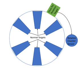
    For having an additional sensor for the rotation counter, you would need to have a separate target that only passes over the 3rd sensor once per rotation. One example of this would be to have something like the following: 

    But as long as you can implement some target that would only pass by the 3rd sensor once per rotation, it doesn't matter how it is achieved. 

    Best Regards, 
    Justin Beigel

  • Hello Justin,

      I am able to get that files but code will open in CSS software or I need to install any other software to access that code.

    Regards,

    Sayali

  • Hello Sayali, 

    Yes you can use CCS to view it. The main file is the main.c under the TIDA00828_Firmware_v3 folder. 

    Best Regards, 

    Justin Beigel

  • Hello Jutin,

       I am able to view the code in CSS. one more think to view output with GUI i.e to make stand alone output what changes should I make.

    can I order LDC0851 rotational knob 32 position eval board . I am not getting option to buy this board.

    Regards,

    Sayali

  • Hi Sayali,

    In order to view the the output separately from the GUI, which I believe is what you are asking, you will need to make sure that the code is configured to interface with the MCU that you are using. Additionally, you will need to find where in the code that the output is being sent to the GUI and change it so that you are able to use the output however you need it.

    You should be able to purchase the LDC0851EVM at the following link here. You just need to login to your ti.com account to be able to place an order. 

    Best,

    ~Alicia

  • Hello Alicia ,

    Yes you are correct I want to view output separately from the GUI for that only I am asking how to do that and do I need to purchase any additional device .Is there any reference for this

             I want to buy below kit , the link which you share that kit already we had purchase

    https://www.ti.com/lit/ug/tidubg5/tidubg5.pdf?ts=1671765747442&ref_url=https%253A%252F%252Fwww.ti.com%252Fsitesearch%252Fen-us%252Fdocs%252Funiversalsearch.tsp%253FlangPref%253Den-US%2526searchTerm%253DLDC0851%2B32%2Bposition%2526nr%253D36

    Regards,

    Sayali

  • Hello Alicia,

      one more thing regarding "LDC0851 Incremental Rotary Encoder" TI design. microcontroller is used in this design just to convert high low output from LDC0851 into numbers o to 32 to display on seven segment right.

    I can use LDC0851 independently right with out microcontroller. just to have high low output right.

    Regards,

    Sayali

  • Hi Sayali,

    Unfortunately, most of our reference designs, like the one you have shared a link to, are not available for sale. We do however, include design files that you may reference if you would like to build it yourself.

    The firmware that you downloaded should show how the digital outputs from the LDC0851 are being handled, from there you should be able to make adjustments to fit your application. Just be sure to keep in mind that the firmware code is specific to the microcontroller that was used in the reference design.

    Regarding your last question, the LDC0851 can be used independently from a microcontroller if all you need from it is whether the output is high/low. There is a great video showing how to use the LDC0851EVM that I have linked to here that shows how to use the EVM without a microcontroller.

    Best,

    ~Alicia