This thread has been locked.

If you have a related question, please click the "Ask a related question" button in the top right corner. The newly created question will be automatically linked to this question.

TMAG5273: Wake-up & sleep with interrupt when a threshold is crossed seems to get stuck

Part Number: TMAG5273
Other Parts Discussed in Thread: , MSP432E401Y, TI-SCB, TMAG5170

Hello

I am testing the TMAG5273 and configured it in W&S mode with interrupt when a threshold is crossed on the X/Y/Z axis.

It seems to be working fine: When I bring a magnet close to the sensor, I can see the interrupt firing. I wrote a test firmware that reads the X/Y/Z magnetic value when an interrupt occurs, print them, and then reconfigure the sensor to not stay in stand-by mode (i.e: set the W&S mode again). When I leave a magnet close to the sensor, I can see that the sensor is continuously generating interrupt

[2022-11-16 12:29:23.062] Magn[uT]: -1182 -37 2117
[2022-11-16 12:29:23.074] Magn[uT]: -1303 -162 2352
[2022-11-16 12:29:23.086] Magn[uT]: -1426 -275 2659
[2022-11-16 12:29:23.098] Magn[uT]: -1545 -441 2939
[2022-11-16 12:29:23.110] Magn[uT]: -1626 -610 3214
[2022-11-16 12:29:23.122] Magn[uT]: -1700 -695 3395
[2022-11-16 12:29:23.134] Magn[uT]: -1666 -801 3361
[2022-11-16 12:29:23.146] Magn[uT]: -1585 -794 3142
[2022-11-16 12:29:23.152] Magn[uT]: -1460 -809 2785
[2022-11-16 12:29:23.164] Magn[uT]: -1252 -867 2403
[2022-11-16 12:29:23.176] Magn[uT]: -1059 -920 2064
[2022-11-16 12:29:23.188] Magn[uT]: -914 -945 1768
[2022-11-16 12:29:23.200] Magn[uT]: -724 -994 1539
[2022-11-16 12:29:23.212] Magn[uT]: -560 -1064 1319
[2022-11-16 12:29:23.224] Magn[uT]: -362 -1136 1134
[2022-11-16 12:29:23.236] Magn[uT]: -219 -1086 909
[2022-11-16 12:29:23.248] Magn[uT]: -43 -1003 684
[2022-11-16 12:29:23.260] Magn[uT]: -8 -899 484

The problem I am facing is very similar to this thread where the sensor appears to become non-responsive after a while (no interrupts generated when a magnet is brought close to the sensor). The time it takes for the sensor to be apparently non-responsive seems to be typically a few minutes without magnet nearby.

The configuration I am using is:

  • DEVICE_CONFIG_1: 0x14 (CONV_AVG set to 32x)
  • DEVICE_CONFIG_2: 0x23 (W&S mode, THR_HYST set)
  • SENSOR_CONFIG_1: 0x71 (X,Y,Z channel enabled, SLEEPTIME of 5ms)
  • X_THR_CONFIG: 0x2 (625uT)
  • Y_THR_CONFIG: 0x2 (625uT)
  • Z_THR_CONFIG: 0x2 (625uT)
  • INT_CONFIG_1: 0x44 (THRSLD_INT set, interrupt through INT)

All the other registers are set to their default values.

When the sensor appears to be non-responsive, I reconfigure the W&S mode, and after that, the interrupts are generated again as expected when a magnet is brought up close (which is not a viable option, I would like to avoid any communication with the sensor unless a threshold is crossed, in order to stay as long as possible in the W&S mode).

To be noted: when doing the reconfiguration, I start by reading the manufacturer ID to ensure the sensor is ready to accept command. The read fail a first time and succeeds the second time, which would indicate to me that

the sensor was still in W&S mode -> the first read wakes it up and the second one succeed while the sensor is awake.

It seems I can work-around this issue by enabling the temperature acquisition (setting T_CH_EN in T_CONFIG register). With the temperature acquisition enabled, I did not encounter any issue: After more than 12 hours without a magnet close to the sensor, interrupts were generated as expected when a magnet was brought close to the sensor.

Instead of enabling the temperature acquisition, if I lower the CONV_AVG to 1x, it also looks like I do not face the issue anymore (although I did not run test with this setting for hours).

The fact that those two settings (temperature acquisition enabled OR CONV_AVG set to 1x) appear to work-around the issue do not make sense to me, most likely they somehow just make the issue less likely. This leads me to wonder whereas I configured the sensor in a "illegal" mode initially? Do you have a recommended configuration to have the W&S mode with interrupt when a threshold is crossed? Do you see anything wrong with the configuration I used?

In case it is relevant, I was doing my testing with a nucleo l432kc board and a MIKROE-5188 dev kit, powered at 3.3V.

Thanks in advance,

Philémon

  • Hi Philémon,

    Thank you for contacting the Sensing Forum!

    I did not have a chance to look at this today, but I will be able to look at it tomorrow.

    Best,

    ~Alicia

  • Hi Philémon,

    I am currently looking into possible solutions for the issue that you are seeing with your current configurations. In the meantime, can you try testing your configurations with only one threshold set to see if that makes a difference?

    Best,

    ~Alicia

  • Hello Alicia,

    Thank you for your reply. I will test that and report back here.

    FYI: I ran some tests monitoring the power supply on the sensor side to see if it could somehow drop below the 1.8V but it does not appear to be the case.

    I also ran a test with the sensor configured in continuous mode, with CONV_AVG to 32x and CRC enabled, with the MCU reading the sensor every 10ms. After more than 15h there was 0 communication error, nor CRC mismatched.

    Cheers,

    Philémon

  • Hello again Alicia,

    So I ran a first test with having only a threshold on the Z axis, but having X/Y/Z axis enabled.

    In this configuration, the sensor became non-responsive pretty quickly:

    • After boot, bring a magnet close -> interrupt trigger
    • Remove the magnet, wait a few minutes
    • Bring the magnet close again -> no interrupt trigger

    After that I ran a test with only a threshold on the Z axis and only the Z axis enabled. In this case, I did not have issue after ~2h30 of sporadically bringing a magnet close to the sensor and ensuring interrupts were triggered as expected.

    I then left the magnet next to the sensor, expecting continuous interrupt. After a bit more than 30 minutes, the sensor stopped generating interrupts.

    Some additional tests that I ran:

    Hooking a multi-meter, I measured:

    • ~2mA in continuous mode
    • ~620uA in W&S mode (with the config from the initial post)
    • ~580uA in stand-by mode

    Having those references, I then left the setup run in W&S mode, without a magnet nearby, and when the sensor did become not-responsive, it was consuming ~350uA.

    The ~350uA I got while the sensor appeared non-responsive do not correspond to the other measurements I made, could it be entering sleep mode or something?

    Cheers,

    Philémon

  • Hi Philémon,

    The current consumption that you measured for when the sensor was unresponsive seems to be too high for sleep mode as sleep mode is generally expected to be in the nA range. 

    I am currently running some tests to see what the issue could be. I did end up running some tests using your configurations on the A2 device and after having it run for most of the day checking to see if the interrupt was still able to trigger, I did not seem to run into this issue.

    Best,

    ~Alicia

  • Hello Alicia,

    Thank you very much for taking the time to run some tests on your side. Did you try to leave a magnet close to the sensor, expecting continuous interrupt to be generated and check after a few hours?

    I had some test running where I do not print the retrieved magnetic data every time a threshold cross is detected, but just increase a counter.

    So when an interrupt occurs:

    • Read X/Y/Z data
    • Increment a counter instead of printing X/Y/Z
    • Reconfigure W&S mode

    I then periodically print the value of the counter & reset it. So that if I encounter the described issue, I would have this counter at 0 at some point.

    In this case, with the configuration from the initial post, it took significantly longer to encounter the issue (while having a magnet continuously close to the sensor): it took more than 3 hours vs a few minutes typically when I did print the magnetic data.

    The difference between printing the magnetic data and just incrementing a counter is that the sensor will spend less time in stand-by mode before being reconfigured in the W&S mode.

    I did not find any info regarding some timing to be respected before re-configuring the W&S mode, is there something particular I should pay attention to? For example, while the sensor is in stand-by, could the reconfiguration in W&S actually be interpreted as ¨trigger a new conversion¨ and the reconfiguration not be taken into account?

    Also, from this thread, it is specified that interrupt should be done through SCL rather than INT if wanting to use drdy while in W&S mode. Are there some similar limitations that I should be aware of while using the W&S with the threshold crossed interrupt enabled?

    I have a TMAG5273EVM that should arrive tomorrow, I will see if I can reproduce on the A2 device.

    Cheers,

    Philémon

  • Hello Philémon,

    Alicia is currently out of the office due to holiday in the US and will not be back until next week, so I am unable to confirm with her if she ran a test leaving the magnet close to the sensor to generate the continuous interrupt. I will relay this information back to her once she is back but for now I will try to address your other questions.

    1 . I did not find any info regarding some timing to be respected before re-configuring the W&S mode, is there something particular I should pay attention to? 

    There is not a requirement for the amount of time required when configuring/reconfiguring the W&S mode on the device.

    2.  Are there some similar limitations that I should be aware of while using the W&S with the threshold crossed interrupt enabled?

    This is something Alicia is looking into internally with the team to see if there is any specific condition that could cause the interrupts on the INT pin to become "unresponsive" or if there are any limitations as mentioned. But it would be a good thing to try on your system and check if the interrupts to the SCL would experience the same issue.

    We should be getting back to you towards the middle of next week, I hope this is okay. Please let us know if there are any other questions that come up. Thank you!

    Best,

    Isaac

  • Hello Isaac,

    Thank you for the update and for your answers.

    Yesterday I received a TMAG5273EVM, that I hooked to my nucleo l432kc and ran my test FW. With both the A1 and A2 version, I could have the issue occur when leaving a magnet continuously close to the sensor. It took ~15 minutes to have the A1 "not responsive" and ~20 minutes with the A2.

    In order to see the state of the SCL/SDA/INT lines when the sensor appears to be not responsive, I toggle a GPIO if no interrupts were detected in the last 20ms and use that to trigger a capture. In all the following figures, the labels of the line are:

    • GPIO: Set to 1 by the MCU as long as interrupts are received. Set to 0 if no interrupts received since 20ms
    • INT: interrupt line controlled by the TMAG5273
    • SDA: SDA line
    • SCL: SCL line

    Expected behavior

    First, I made a few captures to illustrate the expected behavior while a magnet is close to the sensor. Figure 1 shows one sequence of :

    • Interrupt firing
    • MCU reads  conv status & X/Y/Z data
    • MCU reconfigures the W&S mode

    Figure 2 shows the I2C transfer to read the conv status & X/Y/Z data.

    Figure 3 shows the transfer to reconfigure the W&S mode.

    When a magnet is left close to the sensor, the expected behavior is then according to Figure 4, where the sequence from Figure 1 is repeated over and over again.

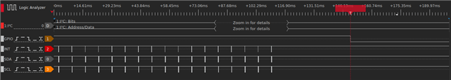
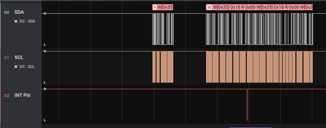
     Fig. 1: Sequence of interrupt, read/reconfigure

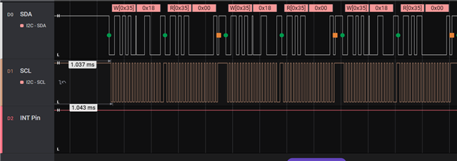
     Fig. 2: Read conv status & X/Y/Z data

    Fig. 3: W&S reconfigure

    Fig. 4: Repeated interrupt sequence while magnet close to the sensor

    According to section 7.3.3 "Latched interrupt through INT" of the datasheet:

    "The interrupt latch is cleared only after the device receives a valid address through the SDA line"

    I would have expected that the interrupt line go back high during the read of the CONV_STATUS register once the TMAG5273 address is read.

    But as can be seen from figure 2, the line goes back low after this transfer, only to go back high when reading the magnetic data and then low again, until the W&S is reconfigured. Is this an expected behavior?

    Instead of having the latched interrupt, I tried to use the pulsed interrupt: I could also have the sensor to be apparently "non-responsive".

    I also tried to use the "Interrupt through SCL" functionality but it did not help neither. Figure 5 shows a transfer triggered by an interrupt through SCL

     Fig. 5: Interrupt through SCL

    Non responsive behavior

    It is interesting to look at the last transfer triggered by a "threshold crossed" interrupt. For this, I trigger on the "GPIO" line going low (controlled by the MCU if no interrupts are detected during the last 20ms). This is shown in Figure 6. From this point, the INT line stays high, even though the magnet is still next to the sensor.

    Figure 7 shows the read of conv status & X/Y/Z data during the last sequence from Figure 6.

    Figure 8 shows the W&S reconfiguration during the last sequence from Figure 6.

     Fig. 6: Trigger when no more interrupt are generated

    Fig. 7: conv status & X/Y/Z read during the last sequence

    Fig. 8: W&S reconfiguration during the last sequence

    It seems that the sensor was reconfigured "as usual". I do not see something different between the last reconfiguration before the tmag is non-responsive and one of the reconfiguration during expected behavior (Figure 3).

    Do you think something is wrong with the reconfiguration mechanism that I use?

    Difference with the TMAG5273EVM/SCB

    In all my tests I used my own board and never the SCB (which I assume you are using for your tests?). When I hooked a multimeter to measure the consumption of the tmag, it seemed to take quite longer before the sensor appears not-responsive. Thus I tried to just add a 10 Ohm resistor on the 3.3V line, which also seemed to make the issue longer to appear.

    Which made me wonder: Are there any components, on the SCB side, that I should include?

    Cheers,

    Philémon

  • Hi Philémon,

    Our team is currently out for the Thanksgiving holidays.  We should be able to look into your question again when we are back next week.

    Thank you,

    Mekre

  • Hi Philémon,

    I am running some tests using the TMAG5273EVM, currently using the A1 device. I tested the scenario that you mentioned, leaving the magnet by the sensor to generate continuous interrupts. I left the magnet there for roughly 2-3 hours and did not see the issue. I have already set up this test case again today in order to leave it for a longer time period to see if the issue would manifest after a longer time period. Looking at figure 2 and 3 that you shared, I was able to get the INTB pin to go back low after the initial interrupt, similar to the behavior shown in these images, and found that the use of delays between the device waking up after a threshold cross and being put back to sleep can cause the INTB pin to go low after the initial interrupt. Additionally, the use of long delays seems to cause the INTB pin to exhibit this nonresponsive behavior sooner versus using shorter delays. 

    If you are using delays between each device read/write call after the device wake-up, I would recommend either removing them or significantly reducing the delay time to see if that makes a difference in when/whether the non-responsive behavior occurs.

    Regarding your question as to possible components needed on the SCB side, the TMAG5273EVM should have everything that you would need to interface with the MCU that you are using. Any additional components on the SCB side are specific to the devices and components used within the SCB.

    Best,

    ~Alicia 

  • Hello Alicia,

    Thank you for the update. I tried to have the reconfiguration in W&S done as fast as possible after an interrupt occurs, i.e: I do not do any read, nor print anything, I just reconfigure in W&S once an interrupt fires.

    In this case, the test FW ran for 2h12 before the interrupt stopped being fired, which is the longest I saw.

    To be clear, when you say:

    Additionally, the use of long delays seems to cause the INTB pin to exhibit this nonresponsive behavior sooner versus using shorter delays. 

    Did you refer to the previous result I got or you did observe this nonresponsive behavior?

    I understood from:

    I left the magnet there for roughly 2-3 hours and did not see the issue

    that you never encountered the issue.

    Could you please tell me exactly the configuration you used for each registers? Is it the one I send in the first post, of:

    • DEVICE_CONFIG_1: 0x14 (CONV_AVG set to 32x)
    • DEVICE_CONFIG_2: 0x23 (W&S mode, THR_HYST set)
    • SENSOR_CONFIG_1: 0x71 (X,Y,Z channel enabled, SLEEPTIME of 5ms)
    • X_THR_CONFIG: 0x2 (625uT)
    • Y_THR_CONFIG: 0x2 (625uT)
    • Z_THR_CONFIG: 0x2 (625uT)
    • INT_CONFIG_1: 0x44 (THRSLD_INT set, interrupt through INT)

    I must be doing something wrong as I can reproduce every time, it is just a matter of how long the test run.

    What I2C bus frequency are you using? I tried 100kHz and 400kHz.

    Once an interrupt trigger, are you doing any read, or any write in addition to the reconfiguration in W&S? Would it be possible to have a look at the code you use?

    If you are using a MSP432, what is the clock speed used? I use a clock of 80MHz on my nucleo (vs the max of 48MHz on the MSP432) , maybe the interrupt can be serviced "too quickly"? Any chance you can try with a board with a faster clock?

    Thank you again for your time,

    Philémon

  • Hi Philémon,

    When I mentioned how the usage of long delays seems to contribute to the nonresponsive behavior, I was referring to the tests that I conducted where I observed this behavior. I had noticed that when I used delays the INTB pin would go low after the initial interrupt, similar to what you observed in Figure 2 & 3. However, after removing those delays, the INTB pin did not exhibit this behavior and after leaving it for roughly 4-5 hours yesterday, the device remained responsive and did not exhibit the nonresponsive behavior. 

    Regarding the configurations that I used, I am using the ones that you shared in your initial post. Additionally, I am using 400kHz for the I2C bus frequency; however, this should not affect the interrupt function of the device. 

    For the tests that I ran, once an interrupt gets triggered, I clear the interrupt, turn on an LED on the SCB board, read the CONV_STATUS register as well as doing a multiple I2C read of registers 0x12 through 0x17 before reconfiguring the device back into W&S mode. When there is no interrupt, the LED gets turned off.

    For the MSP432E401Y clock, I am using the 25-MHz external crystal with the PLL set to 120 MHz. 

    Would you mind sharing a capture that shows the behavior of the SCL, SDA, and INTB with your new configuration where you are only reconfiguring the W&S mode once an interrupt occurs? 

    Best,

    ~Alicia

  • Hello Alicia,

    Thank you for the details.

    One transaction consisting of INT trigger/reconfiguration is shown in Figure 9, which is part of the overall logic shown in Figure 10 while a magnet is left close to the sensor.

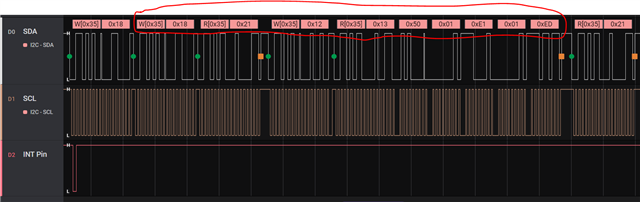
     Fig. 9: Only reconfiguring W&S once an interrupt triggers

    Fig. 10: Continuous interrupt while magnet is close to the sensor

    I currently have a test running with my logic analyser connected to have a look at the last transfer before ¨non-responsiveness¨. It has been running for ~4h30 without issues so far. I will let this run until I can trigger on the non-responsive behavior or until monday morning.

    Yesterday I ran the same test with CONV_AVG=1, W&S with SLEEPTIME=50ms and only the Z axis enabled (which could be a configuration I would probably use in the product the TMAG5273 is destined to be in, depending how the testing goes) and I had no issues after 15 hours of continuous interrupt.

    Sorry if I am being dense but when you say

    When I mentioned how the usage of long delays seems to contribute to the nonresponsive behavior, I was referring to the tests that I conducted where I observed this behavior.

    it means that you did encounter the non-responsive behavior? I mean, you did not just observe the interrupt line going back low, but also the TMAG not triggering interrupt?

    Cheers,

    Philémon

  • Hi Philémon,

    I apologize for the confusion, I did end up seeing both the interrupt going back low and the TMAG5273 not triggering interrupts after a period of time when I used delays, particularly long ones. 

    Let me know if you run into the non-responsive behavior, and I will look further into what else could be causing the behavior.

    Best,

    ~Alicia

  • Hello Alicia,

    Thanks for the precision regarding the non-responsive behavior.

    The test that I was running ended with the tmag being non-responsive after ~23 hours of continuous interrupt with W&S with SLEEPTIME=5ms.

    Figure 11 shows the last few transfers and Figure 12 the last one. One difference between the transfer in Figure 12 and all the other from Figure 11 is the duration of the interrupt line being held low:

    • Transfers from Figure 11: ~108-111 usec
    • Transfer from Figure 12: ~151 usec

    Maybe that is just a coincidence, or something like the time between the Interrupt line going low and when the interrupt is serviced is critical? Or the duration of the overall "interrupt line held low" time is critical (in which case the issue would be harder to observe if using I2C@400kHz instead of I2C@100kHz)?


    Fig. 11: Non responsive behavior with only reconfiguration

    Fig. 12: Last I2C transfer before non-responsive behavior

    The configuration used was with only the Z axis enabled.

    After this test ended up with the tmag non-responsive I tried the following (still only re-configuring W&S when an interrupt occurs):

    • Only Z axis enabled
    • SLEEPTIME of 100ms
    • CONV_AVG=0

    In this case, it took ~10 minutes to have the non-responsive behavior. I then relaunched the same test and again, non-responsive after less than 10 minutes.

    Then, I only changed CONV_AVG to 1 and launched again: Running since 28 hours without issues so far.

    Instead/in addition to some timings when reconfiguring the tmag, the value of CONV_AVG could be a lead?

    Cheers,

    Philémon

  • Hi Philémon,

    When it comes to the CONV_AVG, depending on what sampling rate was chosen, as well as the number of channels enabled, the time it takes for a conversion to finish will very. Depending on the use of delays and/or other timing factors, it could be that after a period of time your microcontroller gets out of sync with the TMAG5273's interrupt signal causing the non-responsive behavior.

    Best,

    ~Alicia

  • Hello Alicia,

    I am not sure I understand your supposition about my MCU getting out of sync with the TMAG5273's interrupt. I can see that at some point, the TMAG5273 is not pulling its interrupt line low, so even if the MCU somehow missed an interrupt, I would still expect to see the line going low.

    Now on the issue itself, what is the next step on your side? As you could reproduce, I have a few questions:

    • Are you looking into a configuration that could workaround the issue?
    • Can you explain what the actual issue is?
    • Is there some sort of errata planned?
    • As it seems that there is an issue on the chip, maybe a new revision of theTMAG is envisioned?

    So far, I can only try some configuration and empirically check whether the issue seems to be more or less frequent but it would be good to have an explanation of what the actual issue is, and also, ideally, a workaround.

    Cheers,

    Philémon

  • Hi Philémon,

    I am going to be reaching out to the team internally to further investigate the reason for the device's behavior as well as possible solutions/workarounds for them. I will keep you updated on what I find out.

    Best,

    ~Alicia

  • Hi Philémon,

    Just to make sure that there is not some kind of issue with the last I2C command not being interpreted by the device correctly, would it be possible for you to rewrite the last I2C transfer when the non-responsive behavior occurs to see if the device resumes (i.e., when the GPIO line goes low, configure the device to go into W&S mode one time)? Alternatively, if the wait time is too long, you could just do double writes of all 0x23 to register 0x1 after the INT pin goes low.

    Best,

    ~Alicia

  • Hello Alicia,

    would it be possible for you to rewrite the last I2C transfer when the non-responsive behavior occurs to see if the device resumes (i.e., when the GPIO line goes low, configure the device to go into W&S mode one time)?

    yes, this is something I did try, to do a reconfiguration once the non-responsive behavior was observed. After the reconfiguration, the TMAG5273 generated interrupts again, until the next non-responsive state.

    Note that the GPIO line is something that I use just for this stress test, in order to see what the last I2C transfer looks like. In real conditions, I will not be expecting continuous interrupts and thus won't be able to monitor their presence.

    Alternatively, if the wait time is too long, you could just do double writes of all 0x23 to register 0x1 after the INT pin goes low.

    I thought about something like this but did not try it because from what I got from the datasheet, the TMAG5273 automatically increases the register address when doing multiple write. This mean that I could not do the two reconfiguration from the same I2C transfers and would need to use two transfers.

    My concern was that after the first transfer to reconfigure the W&S, the TMAG5273 could enter sleep so that the second transfer would just wake it up and leave it in stand-by, basically forcing it into non-responsive behavior. If I understand table 6.11 correctly, I would have a 20us window between the two transfers to avoid the TMAG5273 to enter sleep after the first transfer.

    I will try.

    Cheers,

    Philémon

  • Hi Philémon,

    I know that you mentioned trying both 100kHz and 400kHz for the I2C clock frequency, but generally, which frequency are you using? Also, what is the margin on the I2C start/stop timing?

    Best,

    ~Alicia

  • Hello Alicia,

    I did one try with reconfiguring twice, but unfortunately it looks like the TMAG5273 is entering sleep in between the two transfer. So that the second reconfiguration just wakes the TMAG5273 without being acknowledged. I have a ~40us between the transfer, cf Figure 13.

    Fig. 13: Two reconfiguration of W&S

    but generally, which frequency are you using?

    I am using 100kHz normally.

    what is the margin on the I2C start/stop timing?

    Sorry I do not understand which margin you are talking about, can you give an example?

    Cheers,

    Philémon

  • Hello Philémon,

    Would you be able to try the following sequence of I2C commands to see if this fixes the issue?

    Upon detecting an interrupt:

    • Write to OPERATING_MODE 0x00 (should be the first I2C communication once interrupt is detected)
    • Read of results/registers that you may need (optional)
    • Then put the device back into W&S mode

    Best,

    ~Alicia

  • Hello Alicia,

    Thanks for the suggestion. I have a test setup that is running with those changes (without reading the results registers).

    The interrupt line is going back low in between the setting of stand-by mode and W&S mode (cf figure 14). Other than that, it is running fine so far, but it only has been ~1h of continuous interrupt.

    I will report back after longer hours of testing or if I can trigger on the non-responsive behavior.

    Fig. 14: Set stand-by mode before reconfiguring W&S

    Cheers,

    Philémon

  • Hi Philémon,

    If you notice the unresponsive behavior, as a sanity check, would you be able to do a read of the configuration registers that you have set as well as the CONV_STATUS and DEVICE_STATUS registers? Also just in case the device, for some reason, experienced a power-on reset, write '1' to the POR field in the CONV_STATUS register after powering on the device.

    Best,

    ~Alicia

  • Hello Alicia,

    It did end up non-responsive after a few hours. I did not have a read of the configuration registers when it happened, I will add a dump of all the registers.

    Cheers,

    Philémon

  • Hello Alicia,

    I added a dump of all the registers once I detect that there was no interrupts during the last 20ms. Both the POR field and the 4 error bits of the DEVICE_STATUS register are cleared if needed when initializing the TMAG5273.

    Case 1: When the non-responsive behavior occur, the registers are as follow:

    [2022-12-14 11:47:23.587] Missing interrupt
    [2022-12-14 11:47:23.593] Registers 0x0: 0x14
    [2022-12-14 11:47:23.594] Registers 0x1: 0x23
    [2022-12-14 11:47:23.596] Registers 0x2: 0x71
    [2022-12-14 11:47:23.598] Registers 0x3: 0x0
    [2022-12-14 11:47:23.600] Registers 0x4: 0x2
    [2022-12-14 11:47:23.602] Registers 0x5: 0x2
    [2022-12-14 11:47:23.604] Registers 0x6: 0x2
    [2022-12-14 11:47:23.606] Registers 0x7: 0x0
    [2022-12-14 11:47:23.608] Registers 0x8: 0x44
    [2022-12-14 11:47:23.610] Registers 0x9: 0x0
    [2022-12-14 11:47:23.612] Registers 0xa: 0x0
    [2022-12-14 11:47:23.614] Registers 0xb: 0x0
    [2022-12-14 11:47:23.616] Registers 0xc: 0x6a
    [2022-12-14 11:47:23.619] Registers 0xd: 0x1
    [2022-12-14 11:47:23.621] Registers 0xe: 0x49
    [2022-12-14 11:47:23.623] Registers 0xf: 0x54
    [2022-12-14 11:47:23.625] Registers 0x10: 0x44
    [2022-12-14 11:47:23.627] Registers 0x11: 0x80
    [2022-12-14 11:47:23.629] Registers 0x12: 0x11
    [2022-12-14 11:47:23.632] Registers 0x13: 0xf9
    [2022-12-14 11:47:23.634] Registers 0x14: 0x2
    [2022-12-14 11:47:23.636] Registers 0x15: 0xd8
    [2022-12-14 11:47:23.638] Registers 0x16: 0x1
    [2022-12-14 11:47:23.640] Registers 0x17: 0x3a
    [2022-12-14 11:47:23.642] Registers 0x18: 0x23
    [2022-12-14 11:47:23.644] Registers 0x19: 0x0
    [2022-12-14 11:47:23.646] Registers 0x1a: 0x0
    [2022-12-14 11:47:23.649] Registers 0x1b: 0x0
    [2022-12-14 11:47:23.651] Registers 0x1c: 0x14

    In particular, the DEVICE_STATUS register has the INT_ERR bit set.

    Case 2: If I remove the magnet while the TMAG5273 is operating normally, so that it is expected that there won´t be interrupts anymore, the registers are as follow:

    [2022-12-14 15:35:16.291] Missing interrupt
    [2022-12-14 15:35:16.293] Could not get manufacturer id
    [2022-12-14 15:35:16.314] Registers 0x0: 0x14
    [2022-12-14 15:35:16.316] Registers 0x1: 0x20
    [2022-12-14 15:35:16.318] Registers 0x2: 0x71
    [2022-12-14 15:35:16.321] Registers 0x3: 0x0
    [2022-12-14 15:35:16.323] Registers 0x4: 0x2
    [2022-12-14 15:35:16.325] Registers 0x5: 0x2
    [2022-12-14 15:35:16.327] Registers 0x6: 0x2
    [2022-12-14 15:35:16.329] Registers 0x7: 0x0
    [2022-12-14 15:35:16.331] Registers 0x8: 0x44
    [2022-12-14 15:35:16.333] Registers 0x9: 0x0
    [2022-12-14 15:35:16.335] Registers 0xa: 0x0
    [2022-12-14 15:35:16.337] Registers 0xb: 0x0
    [2022-12-14 15:35:16.339] Registers 0xc: 0x6a
    [2022-12-14 15:35:16.341] Registers 0xd: 0x1
    [2022-12-14 15:35:16.343] Registers 0xe: 0x49
    [2022-12-14 15:35:16.345] Registers 0xf: 0x54
    [2022-12-14 15:35:16.347] Registers 0x10: 0x0
    [2022-12-14 15:35:16.349] Registers 0x11: 0x0
    [2022-12-14 15:35:16.351] Registers 0x12: 0x0
    [2022-12-14 15:35:16.353] Registers 0x13: 0x0
    [2022-12-14 15:35:16.355] Registers 0x14: 0x0
    [2022-12-14 15:35:16.357] Registers 0x15: 0x0
    [2022-12-14 15:35:16.360] Registers 0x16: 0x0
    [2022-12-14 15:35:16.362] Registers 0x17: 0x0
    [2022-12-14 15:35:16.364] Registers 0x18: 0x0
    [2022-12-14 15:35:16.366] Registers 0x19: 0x0
    [2022-12-14 15:35:16.368] Registers 0x1a: 0x0
    [2022-12-14 15:35:16.370] Registers 0x1b: 0x0
    [2022-12-14 15:35:16.372] Registers 0x1c: 0x10

    Note the "Could not get manufacturer id" in case 2 and not in case 1. Before dumping the registers, I do a read of the manufacturer id register in order to wake up the TMAG5273 in case it is in sleep.

    In case 2, as the TMAG5273 keeps operating in W&S mode, it is expected that I would have to do the read twice: one to wake it up, and one to actually retrieve the value.

    In case 1, this read is immediately successfull, which would indicate to me that the TMAG5273 is ready to accept command and thus not in W&S mode even though the OPERATING_MODE of the DEVICE_CONFIG_2 is set to 0x3 (W&S).

    Also, in case 1, the CONV_STATUS register indicate that a conversion is complete (and data is available in registers 0x12-0x17).

    It looks like the TMAG5273 did the conversion, compared to the threshold, but failed to drive the interrupt line for whatever reason.

    Cheers,

    Philémon

  • Hi Philémon,

    Would you be able try the following I2C sequence?

    • Interrupt occurs
    • Read Error bits and write '1' to clear them, if necessary 
    • Put device back into W&S mode

    Best,

    ~Alicia

  • Hi Philémon,

    Can you also try setting the MASK_INTB bit to 0x01?

    Best,

    ~Alicia

  • Hi Philémon,

    I am currently running the following test which has been running for the past 16 hours and seems to be running fine. 

    • DEVICE_CONFIG_1: 0x14
    • DEVICE_CONFIG_2: 0x23 
    • SENSOR_CONFIG_1: 0x71
    • X_THR_CONFIG: 0x2 
    • Y_THR_CONFIG: 0x2 
    • Z_THR_CONFIG: 0x2
    • INT_CONFIG_1: 0x44

    With these configurations, I am running the following I2C communication sequence:

    • Interrupt get detected and cleared 
      • delay for 100 us to give interrupt time to finish clearing
    • Put device into stand-by mode
    • read CONV_STATUS register as well as result registers
    • put device back into W&S mode

    I have also changed the pull-up resister used on the INT pin from 4.7kOhms to 1kOhm.

    I plan to leave it running over the weekend to see if the INT pin stops sending interrupts and will let you know what happens.

    Best,

    ~Alicia

  • Hello Alicia,

    Thanks for the info. I tried this:

    Would you be able try the following I2C sequence?

    • Interrupt occurs
    • Read Error bits and write '1' to clear them, if necessary 
    • Put device back into W&S mode

    but ended up with the non-responsive behavior without having the error bit set (once the non-behavior occurs, the error bit is set).

    This, I do not understand:

    Can you also try setting the MASK_INTB bit to 0x01?

    From what I get from the datasheet, this should be set to 1 to disable the INT pin. Which configuration am I supposed to use with the MASK_INTB set and still have interrupts?

    With these configurations, I am running the following I2C communication sequence:

    • Interrupt get detected and cleared 
      • delay for 100 us to give interrupt time to finish clearing
    • Put device into stand-by mode
    • read CONV_STATUS register as well as result registers
    • put device back into W&S mode

    I did not try to read CONV_STATUS and the result registers in between the "put device into stand-by mode" and "put device back into W&S mode", I guess I will try that if you tell me that your weekend test did not run into the non-responsive behavior. You were using 100kHz for I2C?

    Do you have updates on the condition that can cause this non-responsive behavior? Something to do with the pull-up resistor being too high?

    Cheers,

    Philémon

  • Hi Philémon,

    After leaving my setup over the weekend, I did see that the INT pin stopped sending interrupts. After sharing my results internally, I have been given some possible solutions that I am going to try to see if they solve the issue.

    Some possible reasons for the behavior that is occurring, though testing is still being done to pinpoint the cause, could be either of the following:

    • Pull-up INT resistor is too high/low
    • Device is unable to clear the interrupt properly, as the condition (magnetic field exceeding set threshold) still persists so INT keeps getting triggered 
      • This could be why we see that the INT line goes low in between I2C communications
    • etc.

    I am going to be trying the following 2 possible solutions to see if the issue could be the second bullet point:

    • Possible solution 1 (workaround sequence to allow device to properly clear interrupt):
      • Write to put the device into stand-by mode.
      • Read result registers for X, Y, and Z (both MSB and LSB) – not necessary, but useful to know the result.
      • Read CONV_STATUS register – not necessary, but useful to know the status
      • Write to disable/lower threshold (to prevent persistent threshold cross condition), or move magnet away.
      • Trigger a conversion – to get new results that do not cause threshold crossed condition.
      • Read CONV_STATUS register (to clear interrupt) – actually any i2c transaction would clear the interrupt.
      • Write back the desired threshold
      • Write to put the device back into W&S mode
    • Possible solution 2:
      • Set device to INT pulse

    I know that you mentioned already trying the INT pulse mode and that you still saw the non-responsive behavior, but would you mind sharing more about that test case? I have yet to try this mode to see if this behavior will appear so I am going to be leaving it over night to see what happens.

    For my setup I am using a 400kHz I2C bus. I will give you an update on my setup tomorrow morning.

    Best,

    ~Alicia

  • Hello Alicia,

    I know that you mentioned already trying the INT pulse mode and that you still saw the non-responsive behavior, but would you mind sharing more about that test case?

    I used the same configuration as in the original post, except the INT_STATE bit set to 1. When an interrupt occured, I read the CONV_STATUS & result registers, before reconfiguring the W&S mode. I also tried the "interrupt through SCL" (cf Figure 5), without success. I do not have much more to say on this, maybe you have something specific in mind?

    For my setup I am using a 400kHz I2C bus

    Maybe I was lucky but it seemed to me that the issue occurs faster with 100kHz so it may be better to use 100kHz in order to reduce the overall testing time.

    Cheers,

    Philémon

  • Hi Philémon,

    I will run a test using the 100kHz I2C bus to see if the issue occurs faster. I will let you know what I find out. In the meantime, what is the value of the pull-up resistor that you are using on the INT pin?

    Best,

    ~Alicia

  • Hello Alicia,

    In the meantime, what is the value of the pull-up resistor that you are using on the INT pin?

    I had the issue both with the tmag5273EVM that use a 4.7k and the MIKROE-5188 devkit that use a 10k.

    Cheers,

    Philémon

  • Hi Philémon,

    I was not able to run a test with the 100kHz I2C bus yesterday, but I have it set up now and will leave it over night to see what happens. I will let you know what I find out.

    Best,

    ~Alicia

  • Hi Philémon,

    I ended up trying both possible solution and after a period of time, the INT pin stopped sending interrupts using both a 400kHz I2C bus and a 100kHz I2C bus. I am currently reaching out internally to see what else could be causing this to happen and what a possible fix to this would look like. I will let you know what I find out, though due to the holidays, responses may be delayed.

    Thank you for your patience.

    Best,

    ~Alicia

  • Hello Alicia, happy new year!

    Do you know when I can expect some news regarding the issue on the TMAG5273?

    Cheers,

    Philémon

  • Hi Philémon,

    I am still looking into why, after a period of time, the INT pin on the TMAG5273 stops sending interrupts, and if I find something out, I will let you know.

    However, an alternative that you could try is instead of using W&S mode, you can use sleep mode and wake the device up using your MCU. I have a setup of this that is currently working and that I will leave over the weekend to ensure that no issues arise after a long period of use. The benefit of using this method, is that you can completely customize the time the device spends asleep instead of using the preprogramed times specified by the SLEEPTIME field in SENSOR_CONFIG_1 register.

    The setup that I am currently using looks something like the following:

    1. Initialize and power device for use with MCU.
    2. Run a brief W&S cycle (I let it run for 10ms, but a couple ms should be fine) to avoid I2C address glitch in sleep mode
      • This only needs to be run once initially
    3. Wake up device and configure registers
      • I used the same configurations that you have listed in your initial post with the only difference being that I have it set to INT pulse.
        • DEVICE_CONFIG_1_ADDRESS   = 0x14
        • DEVICE_CONFIG_2_ADDRESS   =  0x20
        • SENSOR_CONFIG_1_ADDRESS = 0x71
        • SENSOR_CONFIG_2_ADDRESS =  0x00
        • X_THR_CONFIG_ADDRESS        =  0x02
        • Y_THR_CONFIG_ADDRESS        = 0x02
        • Z_THR_CONFIG_ADDRESS        = 0x02
        • INT_CONFIG_1_ADDRESS          = 0x64
    4. Device gets put into sleep mode for 10ms 
    5. Wake-up device (delay for time specified by datasheet, 50us, to give device time to get into stand-by mode)
    6. Trigger a conversion
    7. Delay for some time (I have it set for 1ms) 
    8. Wait for conversion is complete
      • For this, I have a while loop that reads CONV_STATUS the RESULT_STATUS but until it reads back a '1' 
    9. Once this is done I put the device back into sleep mode

    For the interrupt portion, when a threshold cross is detected, I have an interrupt service routine (ISR) set by the MCU to interrupt on a falling edge for when the INT pin on the TMAG5273 goes low. In this ISR, I just clear the interrupt and read the CONV_STATUS and result registers. The ISR tends to get triggered sometime between Step 6 and Step 7 which, based on my setup, seemed necessary for it to trigger.

    I have attached a waveform for what the I2C communication and INT pin looks like from when the device gets woken up to when it goes back to sleep below:

    Figure 1: TMAG5273 wakes up

    Figure 2: Wait for data conversion to be complete

    Figure 3: ISR gets triggered (threshold cross is detected)

    Figure 4: TMAG5273 gets put back into Sleep mode

    Figure 5: Overall I2C communication

    For this setup, I am using the TMAG5273EVM with the TI-SCB and the I2C bus clock set to 100kHz. I will give you an update on how this setup lasts over the weekend. Thank you for your patience.

    Best,

    ~Alicia

  • Hello Alicia,

    Thank you for the answer and for the proposed alternative.

    The benefit of using this method, is that you can completely customize the time the device spends asleep

    That is true, but the big downside is that offloading the logic to the MCU will add a lot more traffic on the I2C bus proportionally to the desired SLEEPTIME, and it will also prevent the MCU to stay in deep sleep.

    Regarding the proposed alternative:

    • Why doing steps 4/5/6/8? From what I understand, you just need to (excluding the boot sequence)
      - Wake-up the TMAG5273
      - Configure the registers
      - Wait 1ms
      - If interrupt occured, threshold was crossed (optionally read result registers if there was an interrupt)
      - Put back the TMAG5273 in sleep mode
      - MCU sleep for (SLEEPTIME - 1)ms
    • It still uses the W&S mode to detect the threshold crossed during the 1ms window where the TMAG5273 is not in sleep mode. As the root cause of the issue is not known, nothing guarantees that the sensor is not in the "not responsive" behavior just after having been woken up AFAIK (although, granted that if it ever happens, the cycle of putting it back to sleep and then re-configuring it should work).

    • At this point, I would just put the device in "Continuous measure" mode and use the interrupt in "data ready" mode (INT_CONFIG_1 = 0xA4 or 0x84) so that when the TMAG5273 is woken up from sleep mode, the ISR would just trigger a read of the results registers as soon as the first sample is available and the MCU will do the comparison to the desired threshold and then put it back to sleep.

    But that is not a viable alternative due to what I mentioned above with the added traffic/deep sleep prevention.

    Cheers,

    Philémon

  • Hi Philémon, 

    For the microcontroller that you are using, would it be possible to put it in sleep mode and have the microcontroller wake-up based on some interrupt timer?

    If so you could put your microcontroller into sleep mode and have it wake-up in intervals so that it can wake-up the TMAG5273 from sleep mode to check for a threshold cross.

    To clarify steps 4/5/6/8:

    • Step 4 is used to begin the start of the whole cycle where the TMAG5273 would be put into sleep mode for some amount of time before being woken up to check for an interrupt
      • Note: only steps 5-9 gets repeated as for all iterations excluding the first, step 9 puts the device into sleep mode
    • Step 5 is used to wake the device up from sleep mode 
    • Step 6 is needed as because the device has woken up from sleep mode, it gets put into stand-by mode, so a data conversion needs to be triggered so the device can check for an interrupt
      • Note: this step can be replaced by putting the device into continuous measure mode to allow for the device to take readings
    • Step 8 is more of a safe-guard to ensure that enough time has passed for a data conversion to complete, so if step 7 has a long enough delay time, this step may be unnecessary.

    Best,

    ~Alicia

  • Hi Philémon,

    I ended up running another test in W&S mode, this time using a 1MHz I2C bus with the following configurations:

    • DEVICE_CONFIG_1: 0x14 (CONV_AVG set to 32x)
    • DEVICE_CONFIG_2: 0x23 (W&S mode, THR_HYST set)
    • SENSOR_CONFIG_1: 0x71 (X,Y,Z channel enabled, SLEEPTIME of 5ms)
    • X_THR_CONFIG: 0x2 (625uT)
    • Y_THR_CONFIG: 0x2 (625uT)
    • Z_THR_CONFIG: 0x2 (625uT)
    • INT_CONFIG_1: 0x64 (THRSLD_INT set, INT pulse, interrupt through INT)

    I left this setup for over a week and the INT pin continued to send interrupts as expected. After talking with the team internally, we believe that the reason that the issue that was seen occurred due to an asynchronous relationship between the internal system clock of the microcontroller and the i2c clock. With a fast enough I2C clocks, the I2C writes to move the device into W&S mode fast enough that the contention between the device's transition into W&S mode vs wakeup on I2C access does not occur.

    If the previously proposed alternative of using sleep mode and waking the device up with your microcontroller is not a viable option for your system, I would recommend using a 1MHz I2C bus instead of 100kHz/400kHz.

    Best,

    ~Alicia

  • Hello Alicia,

    Thanks for the update.

    Using a 1Mhz I2C clock is not possible for me as I have a bunch of other sensors on the bus, the majority of which only supports up to 400kHz (and I cannot use a dedicated I2C bus for the TMAG due to no more I/O available). I could try it on my l432kc/TMAG5273EVM setup though.

    Regarding offloading the logic of the W&S mode to the MCU, in case that was not clear: I did not mean that deep sleep will be prevented at all, but that the MCU will only be able to sleep for short period of time (which might be ok, but the huge traffic added on the bus is not).

    On your side, is the internal investigation ongoing? Is there some sort of errata planned? Or an updated version of the TMAG5273 planned (assuming the root cause is understood)?

    Thank you for your time,

    Philémon

  • Hi Philémon,

    While I was able to replicate what you have been seeing using the TMAG5273EVM and TI-SCB that I have been using as well as some code that I wrote for this scenario, the team internally has not been able to replicate this issue in their testing of the TMAG5273 device which was what led us to believe that this issue occurs due to an asynchronous relationship between the internal system clock of the microcontroller and the i2c clock. 

    When you say that there are no more I/O available, does that mean there are no more I/O pins that can be used for i2c or that there are no more available I/O pins at all? 

    Best,

    ~Alicia

  • Hello Alicia,

    this issue occurs due to an asynchronous relationship between the internal system clock of the microcontroller and the i2c clock.

    I have no clues what this means, where does this comes from? Are you talking about my MCU or something inside the TMAG5273?

    When you say that there are no more I/O available, does that mean there are no more I/O pins that can be used for i2c or that there are no more available I/O pins at all? 

    No I/O at all. But would that make a difference if there were I/O available even though they could not be used for i2c?

    Cheers,

    Philémon

  • Hello Philémon,

    Sorry for the confusion here, but the answer is something within the TMAG5273. The device has an internal oscillator used within the device for various things. One of them is moving data received by the I2C bus to the other digital portions of the device. The team at the moment theorizes that there could be some sort of race condition at lower i2c speeds that cause the interrupts to become inactive.

    We have not been able to replicate this issue at 1MHz i2c, and the team has not been able to replicate this issue via simulation. Which makes it difficult to find the exact scenario that could be causing the inactivity issue you are seeing.

    I believe Alicia was inquiring about the I/O port availability left on your MCU so that she could recommend perhaps using another device like TMAG5170. This device has a SPI interface instead of i2c.

    Best,

    Isaac 

  • Hello Isaac,

    Thank you for the details!

    The TMAG5170 would not work as I would like it to be powered at 1.8V, but I would have other, cheaper, alternatives (but not from TI). Anyway, thanks for mentioning it.

    Cheers,

    Philémon

  • Hello Philémon,

    I understand. Unfortunately for now it seems like the other alternatives might be the way to go as we find the exact source of the problem. Sorry there was not much we could do but thank you for all the info during the debug process it was very helpful.

    Best,

    Isaac

  • Hello Isaac,

    Just to be clear, the cheaper alternatives I mentioned would still be more expensive than the TMAG5273, which is perfect for my use case on paper.

    I am currently using a workaround of "periodically re-configuring the TMAG5273 in W&S mode" which is acceptable for my use case, although not ideal.

    At this point, it seems that I will have to keep using this workaround, unless:

    1) The root cause is understood and a "proper" workaround is proposed

    2) It is possible that the TMAG5273 ends up in a worst state than just being non-responsive until reconfigured (something like needing a POR in certain conditions)

    As long as 2) cannot happen, I will most likely keep the TMAG5273. So is 2) a possibility? I understand that it is hard/impossible to answer this without first understanding the root cause, but could you tell me if other problematic cases are identified during your internal investigation?

    Sorry there was not much we could do but thank you for all the info during the debug process it was very helpful.

    No worries, and thanks to you and Alicia for your responsiveness and transparency, this is very much appreciated.

    Cheers,

    Philémon

  • Hey Philémon,

    That is good information thanks for sharing.

    As long as 2) cannot happen, I will most likely keep the TMAG5273. So is 2) a possibility? I understand that it is hard/impossible to answer this without first understanding the root cause, but could you tell me if other problematic cases are identified during your internal investigation?

    You are correct, its difficult to say with certainty until we are able to root cause the issue. But as far as we have seen during testing, a POR has not been required in order to get the device into a functional state again.

    I will keep you posted on this thread with any new developments or if we come across any other problems are identified during our internal investigation process.

    Best,

    Isaac