Other Parts Discussed in Thread: AWR2944
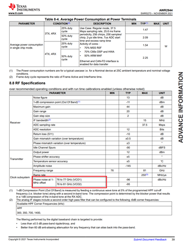
In automotive mrr demo, I want to mitigate the inteference of two radars sensors by using different frequency band for each of sensor.
In configuration file mrr_config_chirp_design_USRR30.h of 1st sensor, I set the START_FREQ_GHZ to 76.51 and FREQ_SLOPE_MHZ_PER_US to 50.01
/*! @brief Ultra short range chirp profile - 20 m range, 4.3cm resolution. better angular resolution,  approximately 18kmph max - vel. */
#define PROFILE_USRR_PROFILE_ID              (1U)
#define PROFILE_USRR_HPFCORNER_FREQ1_VAL     RL_RX_HPF1_175_KHz
#define PROFILE_USRR_HPFCORNER_FREQ2_VAL     RL_RX_HPF2_350_KHz
#define PROFILE_USRR_RX_GAIN_VAL             (30U)
#define PROFILE_USRR_DIGOUT_SAMPLERATE_VAL   (12500U)
#define PROFILE_USRR_ADC_SAMPLE_VAL          (512U)
#define PROFILE_USRR_IDLE_TIME_VAL           (500U)
#define PROFILE_USRR_RAMP_END_TIME_VAL       (4400U)
#define PROFILE_USRR_START_FREQ_GHZ          (76.51f)
#define PROFILE_USRR_START_FREQ_VAL          (CONV_FREQ_GHZ_TO_CODEWORD(PROFILE_USRR_START_FREQ_GHZ))
#define PROFILE_USRR_TXOUT_POWER_BACKOFF     (0U)
#define PROFILE_USRR_TXPHASESHIFTER_VAL      (0U)
#define PROFILE_USRR_FREQ_SLOPE_MHZ_PER_US   (51.01f)
#define PROFILE_USRR_FREQ_SLOPE_VAL          (CONV_SLOPE_MHZ_PER_US_TO_CODEWORD(PROFILE_USRR_FREQ_SLOPE_MHZ_PER_US))
#define PROFILE_USRR_TX_START_TIME_VAL       (100U)  // 1us
#define PROFILE_USRR_ADC_START_TIME_VAL      (300U)  // 4.8 us
#define PROFILE_USRR_LAMBDA_MILLIMETER       (MMWDEMO_SPEED_OF_LIGHT_IN_METERS_PER_USEC/PROFILE_USRR_START_FREQ_GHZ)

#define CHIRP_USRR_0_PROFILE_ID                (1U)
#define CHIRP_USRR_0_START_INDEX               (256U + 0U)
#define CHIRP_USRR_0_END_INDEX                 (256U + 0U)
#define CHIRP_USRR_0_START_FREQ_VAL            (0U)
#define CHIRP_USRR_0_FREQ_SLOPE_VAL            (0U)
#define CHIRP_USRR_0_IDLE_TIME_VAL             (0U)
#define CHIRP_USRR_0_ADC_START_TIME_VAL        (0U)
#define CHIRP_USRR_0_TX_CHANNEL                (TX_CHANNEL_1_ENABLE)

#define CHIRP_USRR_1_PROFILE_ID                (1U)
#define CHIRP_USRR_1_START_INDEX               (256U + 1U)
#define CHIRP_USRR_1_END_INDEX                 (256U + 1U)
#define CHIRP_USRR_1_START_FREQ_VAL            (0U)
#define CHIRP_USRR_1_FREQ_SLOPE_VAL            (0U)
#define CHIRP_USRR_1_IDLE_TIME_VAL             (0U)
#define CHIRP_USRR_1_ADC_START_TIME_VAL        (0U)
#define CHIRP_USRR_1_TX_CHANNEL                (TX_CHANNEL_2_ENABLE)


#define CHIRP_USRR_2_PROFILE_ID                (1U)
#define CHIRP_USRR_2_START_INDEX               (256U + 2U)
#define CHIRP_USRR_2_END_INDEX                 (256U + 2U)
#define CHIRP_USRR_2_START_FREQ_VAL            (0U)
#define CHIRP_USRR_2_FREQ_SLOPE_VAL            (0U)
#define CHIRP_USRR_2_IDLE_TIME_VAL             (0U)
#define CHIRP_USRR_2_ADC_START_TIME_VAL        (0U)
#define CHIRP_USRR_2_TX_CHANNEL                (TX_CHANNEL_3_ENABLE)
in configuration file mrr_config_chirp_design_USRR30.h of 2nd sensor, I set the START_FREQ_GHZ to 78.76 and FREQ_SLOPE_MHZ_PER_US to 50.01
/*! @brief Ultra short range chirp profile - 20 m range, 4.3cm resolution. better angular resolution,  approximately 18kmph max - vel. */
#define PROFILE_USRR_PROFILE_ID              (1U)
#define PROFILE_USRR_HPFCORNER_FREQ1_VAL     RL_RX_HPF1_175_KHz
#define PROFILE_USRR_HPFCORNER_FREQ2_VAL     RL_RX_HPF2_350_KHz
#define PROFILE_USRR_RX_GAIN_VAL             (30U)
#define PROFILE_USRR_DIGOUT_SAMPLERATE_VAL   (12500U)
#define PROFILE_USRR_ADC_SAMPLE_VAL          (512U)
#define PROFILE_USRR_IDLE_TIME_VAL           (500U)
#define PROFILE_USRR_RAMP_END_TIME_VAL       (4400U)
#define PROFILE_USRR_START_FREQ_GHZ          (76.51f)
#define PROFILE_USRR_START_FREQ_VAL          (CONV_FREQ_GHZ_TO_CODEWORD(PROFILE_USRR_START_FREQ_GHZ))
#define PROFILE_USRR_TXOUT_POWER_BACKOFF     (0U)
#define PROFILE_USRR_TXPHASESHIFTER_VAL      (0U)
#define PROFILE_USRR_FREQ_SLOPE_MHZ_PER_US   (51.01f)
#define PROFILE_USRR_FREQ_SLOPE_VAL          (CONV_SLOPE_MHZ_PER_US_TO_CODEWORD(PROFILE_USRR_FREQ_SLOPE_MHZ_PER_US))
#define PROFILE_USRR_TX_START_TIME_VAL       (100U)  // 1us
#define PROFILE_USRR_ADC_START_TIME_VAL      (300U)  // 4.8 us
#define PROFILE_USRR_LAMBDA_MILLIMETER       (MMWDEMO_SPEED_OF_LIGHT_IN_METERS_PER_USEC/PROFILE_USRR_START_FREQ_GHZ)

#define CHIRP_USRR_0_PROFILE_ID                (1U)
#define CHIRP_USRR_0_START_INDEX               (256U + 0U)
#define CHIRP_USRR_0_END_INDEX                 (256U + 0U)
#define CHIRP_USRR_0_START_FREQ_VAL            (0U)
#define CHIRP_USRR_0_FREQ_SLOPE_VAL            (0U)
#define CHIRP_USRR_0_IDLE_TIME_VAL             (0U)
#define CHIRP_USRR_0_ADC_START_TIME_VAL        (0U)
#define CHIRP_USRR_0_TX_CHANNEL                (TX_CHANNEL_1_ENABLE)

#define CHIRP_USRR_1_PROFILE_ID                (1U)
#define CHIRP_USRR_1_START_INDEX               (256U + 1U)
#define CHIRP_USRR_1_END_INDEX                 (256U + 1U)
#define CHIRP_USRR_1_START_FREQ_VAL            (0U)
#define CHIRP_USRR_1_FREQ_SLOPE_VAL            (0U)
#define CHIRP_USRR_1_IDLE_TIME_VAL             (0U)
#define CHIRP_USRR_1_ADC_START_TIME_VAL        (0U)
#define CHIRP_USRR_1_TX_CHANNEL                (TX_CHANNEL_2_ENABLE)


#define CHIRP_USRR_2_PROFILE_ID                (1U)
#define CHIRP_USRR_2_START_INDEX               (256U + 2U)
#define CHIRP_USRR_2_END_INDEX                 (256U + 2U)
#define CHIRP_USRR_2_START_FREQ_VAL            (0U)
#define CHIRP_USRR_2_FREQ_SLOPE_VAL            (0U)
#define CHIRP_USRR_2_IDLE_TIME_VAL             (0U)
#define CHIRP_USRR_2_ADC_START_TIME_VAL        (0U)
#define CHIRP_USRR_2_TX_CHANNEL                (TX_CHANNEL_3_ENABLE)
START_FREQ_GHZ and FREQ_SLOPE_MHZ_PER_US are the only parameters I changed. After these change, I observe that the 1st radar sensor cannot detect any objects any more, and the 2nd radar sensor shows some incorrect detected results. Both radar sensor work abmornally.
Can you please check how to set different frequency band to mitigate interference in automotive mrr demo?


