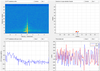
Other Parts Discussed in Thread: IWR6843ISK-ODS
Hi TI Customer Support,
I am a beginner student studying radar. So please escuse me if the question is a bit stupid.
I am using IWR6843ISK-ODS with DCA1000EVM capture board. I have a question.
First, I was able to check the corresponding result through the mmwave studio.

For machine learning, I intend to produce the above "2d fft image" through MATLAB.
This is to be solved by accessing raw data by referring to the document swra581b (9.2).
Therefore, I modified the MATLAB Example as follows.
-------------------------------------------------------------------------------
-------------------------------------------------------------------------------
ADC Bits 16, complex1x, ADC sample 256, No of chirp Loops: 128, No of frame 8
I followed the above specifications, so 32768(ADC sample(256) x No. of chirp(128)) data in one frame.
But I can't see the same image in MATLAB as I saw in mmwave studio.
What is wrong?

