A related question is a question created from another question. When the related question is created, it will be automatically linked to the original question.
If you have a related question, please click the "Ask a related question" button in the top right corner. The newly created question will be automatically linked to this question.
Is DRV5055 capable of sensing changing magnetic field at 10000rpm motor speed, if the magnetic field is within the sensor limit?
The sensor is linear in nature, whereas its application would be position sensing of magnet. Will there be any delay in the output of sensor at 10000rpm?
To use the sensors at temperatures below -40C you would need to evaluate and characterize performance within your system since this exceeds the published operating range of these devices.
Is there any document or tool which can give idea on diametric ring magnet dimensions (Diameter X Thickness & material)? (proximity tool having some bugs) And DRV5055 has to be kept <1mm apart and where it can still detect the field without going out of range > +/- 169mT?
Unfortunately we don't have any sort of reference literature like this. Since all three of these variables can very directly change the observed field at your specified range, it might be easiest to provide some guidance if you could constrain one of the parameters. If you have a preferred magnet vendor with a typical material you would use and an inner diameter that would fit your motor shaft, it might be easier to provide some estimates for outer diameter and thickness.
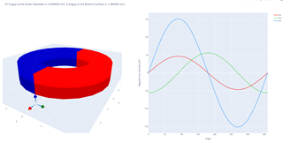
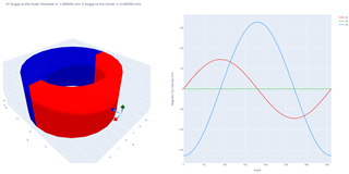
I made an assumption that you were interested in an off-axis placement for this setup given that a ring magnet is typically inserted over a rotating motor shaft. I simulated using an outer diameter of 10 mm, with a 6 mm inner diameter and a thickness of 2 mm. Using the maximum remanence for an N42 magnet (1330 mT), I placed my sensor location 1 mm below the outer diameter edge of the magnet. This produced the following results:
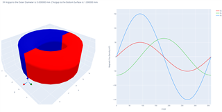
We could similarly switch to the SmCo magnet (with a remanence of 1020 mT). Using the same diameters and placement, I have to increase magnet thickness to 4.4 mm to obtain similar results
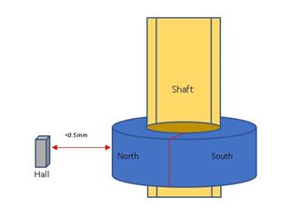
1. Actually I am looking for DRV5055 sensor placement, like below image
So the size of magnet should be such that the flux are within 168mT at < 0.5mm distance.
Same criteria we can assume material as N42 & SmCo24 with inner diameter as 6mm.
Q2. The above simulation results gives idea on the 3D hall sensor output and I got one different question based on your results is there anyway to make z-axis values, just one value/peak constant value at that particular location (1 mm from z-axis as taken in example). I think it will also give information on the position in z direction, how much it is offset w.r.t z-axis, but in 90 degree period we dont have any idea where it was placed as it will be sine in nature?
The field in the provided plot represents the observed field in each direction (X,Y,&Z) as the magnet rotates. Of particular interest with DRV5055 is the Z component, which is the field vector in the direction of sensitivity for the device.
With the setup in this tool that I am using, I am not able to parameterize the dimensions of the magnet, so a plot of peak value vs. outer diameter or thickness is not possible. Tracking down particular magnet sizes is more of a guess and check process.
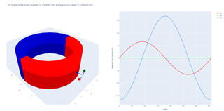
For the N52 magnet, I was able to identify that 7.5 mm OD, 6 mm ID, and 3 mm thickness will produce the following behavior. Note that I did rotate the sensor relative to your image so that the Z direction of the sensor is properly aligned to your diagram. The peak value observed here is 167.7 mT
Since N52 material has such a strong magnetization, it might be more practical to obtain a magnet with SmCo. This material allowed me to use 8 mm OD, 6 mm ID, and 4 mm thickness to obtain a peak input value of 164.2 mT.
As a general rule, however, the difference of the OD to ID creates the most significant change in the observed peak value. I tried making steps of 0.5 mm, until I found something close to your target peak value. I then adjusted the thickness to get as close to your target as possible.
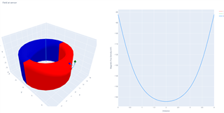
To see the effect of vertical error, I am able to sweep position linearly at a fixed range near the magnet. I've hidden the plots for the X and Y component for clarity. In the next plot, I've move the magnet linearly past the sensor from -2 to +2 mm. The ideal alignment matching the rotation simulations correlates to the 2 mm displacement.
From this we see that +/- 0.5 mm tolerance in placement will result with up to 3 mT reduction in peak input field strength, and this reduction in input strength becomes more dramatic as the placement error increases.