This thread has been locked.

If you have a related question, please click the "Ask a related question" button in the top right corner. The newly created question will be automatically linked to this question.

TMAG5170-Q1: TMAG5170 Queries

Part Number: TMAG5170-Q1
Other Parts Discussed in Thread: DRV5055, TMAG5170, TMAG5110, TMAG5111
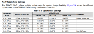
  1. Is TMAG5055 capable to use like encoder? Can it detect changing magnetic field at 10000rpm?  (if the magnetic field is within the sensor limit)
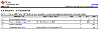
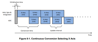
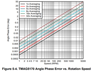
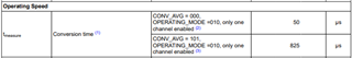
  2. The sensor is linear in nature, whereas its application would be position sensing of magnet. Will there be any delay in the output of sensor at 10000rpm?
  • Prathmesh,

    DRV5055 and TMAG5170 can both be used in angle encoder applications.  DRV5055 is only sensitive to a single field component, so angle measurements require two devices.  One the other hand, TMAG5170 is a 3D sensor and can capture the field of all three vector components.  There should always be at least two which may be used for angle calculations, but amplitude correction may be necessary to provide normalized inputs for the angle calculation.  

    DRV5055 is an analog output device with a sensing bandwidth of 20 kHz.  TMAG5170 is a digital output device and the maximum sample rate with two channels is 13.3 kSPS.  

    DRV5055 (propogation delay is 10 us)

    TMAG5170 - (2 Ch. sample time is approx. 75 us.)

    Using a 10 kRPM rotation, we would see 167 rotations per second.  It is plausible that either device might be used.  To improve angle calculations with TMAG5170, it may be desired to increase the sample averaging, but this will increase total sample duration and add extra latency.

    Thanks,

    Scott

  • Thank you ,

    So they can be used for position sensing and encoder application.

    There should always be at least two which may be used for angle calculations, but amplitude correction may be necessary to provide normalized inputs for the angle calculation.
    • This point is for DRV5055,right?

    • Also how can I understand and relate the below graphs with the propagation delay at vertical 10mm gap at 10k rpm

    https://www.ti.com/lit/an/slya059/slya059.pdf?ts=1673848166474&ref_url=https%253A%252F%252Fwww.ti.com%252Fproduct%252FTMAG5170 
    Figure 2-4. Linear Position Sweep With Increased Magnet Thickness

    In short, if magnet is kept 7mm or 10mm apart from the sensor and motor is rotating at 10k rpm. How will sensor see it? Will it miss to sense magnetic field reading? How to take into account those factors?

    • Also, do we have 'Hall-effect magnetic field calculator' for 'diametric magnet'? like below link.
      www.ti.com/.../DRV5055
  • To capture angle data using a linear Hall-effect device, it is necessary to have two outputs which are 90 degrees out of phase.  Since DRV5055 is only sensitive to the Z-axis component, it will require two devices mechanically separated by 90 degrees.  Placed by a rotating diametric magnet, this will produce a sine/cosine relationship between the two outputs.  This provides the necessary inputs required for an arctangent calculation.  TMAG5170 has 3 mutually orthogonal Hall elements integrated in the same package.  This allows a single device to be used to capture the needed field data since the X, Y, and Z magnetic field components are naturally 90 degrees separated in phase.  

    The referenced plots are missing in your reply, but propagation delay will result in some fixed phase delay between the actual angle of the magnet and the result of the angle calculation.  For the highest degree of accuracy in position control at such speeds, it is necessary to use the propagation delay with the total communication/calculation time to account for the change in the magnet position.  Otherwise the resulting angle calculation will always lag behind the real position of the magnet.  This is discussed in the following app note

    https://www.ti.com/lit/an/sbaa539/sbaa539.pdf

    The linked document SLYA059 is specific towards a magnet which is traveling in a linear path near the sensor.  The plots shown in this document are using an axial polarized magnet with no rotation.  If this type of magnet were placed a the outer circumference of a rotating wheel/gear then the resulting response would be somewhat similar to the plots in this document.  This is not typically the approach used for angle encoding, however.  Rather the magnet is centered on the axis of rotation and the sensor is placed nearby such that the magnet does not leave the vicinity of the sensor. 

    It is possible for the sensor to "miss" the passing magnet if the field changes fast enough.  All Hall-effect devices must integrate the input signal for a short period.  The resulting conversion will be an average value of the field during the entire input integration portion of the sampling time.  For TMAG5170 this is represented in the following image from the datasheet:

    There is a tool which you might find helpful here:

    https://www.ti.com/tool/HALL-PROXIMITY-DESIGN

    Thanks,

    Scott

  • Thank you ,

    The linked document SLYA059 is specific towards a magnet which is traveling in a linear path near the sensor.  The plots shown in this document are using an axial polarized magnet with no rotation.  If this type of magnet were placed a the outer circumference of a rotating wheel/gear then the resulting response would be somewhat similar to the plots in this document.  This is not typically the approach used for angle encoding, however.  Rather the magnet is centered on the axis of rotation and the sensor is placed nearby such that the magnet does not leave the vicinity of the sensor. 

    I was looking for a diametric magnet placed orthogonally.

    What is the maximum rotation speed limit for TMAG5170 sensor placed orthogonally to diametric magnet and DRV5055 sensor(2 sensor placed 90 deg apart) for angle measurement?

  • The maximum speed on TMAG5170 depends on how much averaging you need to achieve your accuracy goals and the total "look ahead" you can manage.  

    The document I linked previously has a plot which you can use as a reference:

    This plot only considers the total time required to complete one conversion and the respective change in angle that would occur based on the rotation speed.  

    In high speed systems, the controller must be able to forward predict the position based on known speed information.  The maximum speed will be set by the accuracy requirements in your system, and the ability of your algorithm to predict current position based on the sensor data (which has propagation delay).  Ideally, however, the magnet should rotate less than 180 degrees during the integration period of the device, and I would probably try to target a delay less than 45 degrees as a starting point.

    DRV5055 is a linear analog device, however.  The operating bandwidth is 20 kHz, which should easily accommodate 10 kRPM.

  • X-axis and Y-axis is sensing the diametric magnet fields to provide angle output.
    Not sure if this is valid but what will z axis hall sensor sensing from the diametric magnet fields at 10mm apart? Will it sense any magnetic field? What will be intensity of the field lines (if atall) going through z-axis?

  • Prathmesh,

    Below is an image of an on-axis rotation, where the magnet is centered on the axis of rotation:

    With the sensor placed below the magnet, also on this axis of rotation, the field from the magnet will be parallel to the face of the magnet and directed towards the S pole of the magnet.  As the magnet rotates, and ideal sine/cosine will emerge for the X and Y axes.  Since the vector is parallel to the magnet in this position there is no Z-component. 

    In practice, your system tolerances and outside influencers, such as the earth's magnetic field, may result with some small amount of field observed in the Z direction.  This should remain very low, but it is hard to quantify for every magnet/air gap/system.  This portion of the field may be used for predictive maintenance.  However, this location is not always ideal for all designs, and some systems require that the sensor be placed off center.  This will still produce X and Y fields, but their amplitudes may be mismatched.  In this second case, there will also an increase on the Z component.  This will change depending on the location of the sensor and the shape and material of the magnet.

    Thanks,

    Scott

  • Thank you ,

    I did use the above tool.

    There is a tool which you might find helpful here:

    https://www.ti.com/tool/HALL-PROXIMITY-DESIGN

    But I am not able to get the output from it.I tried to change the range settings 0,1,2.

    Once I click on Calculate B-field & Vout. I am getting Run-time error 9.

    I have installed FEMM.

  • Prathmesh,

    There appears to be a bug in the latest revision, and I have notified those responsible for the tool.  I believe you are attempting to find the ideal range for your specified magnet.  I have tried to simulate your settings using another simulation tool I have access to.  

    In the image on the left it shows the 20 mm diameter magnet with a 10 mm gap from the sensor location. The distance sweep starts in this position and then moves the magnet closer to the sensor location.  (This sensor marker does not account for package sizes).  Since the magnet is not rotating in this simulation, we see that the field is entirely in the Y direction.  The final position is 10 um above the sensor to avoid the sensor entering the magnet space.  

    This N52 magnet is quite large, so it produces a fairly strong field which would saturate the inputs of TMAG5170A1 when the magnet is closer than 7.5 mm to the sensing element.  

    Thanks,

    Scott

  • Thank you ,

    There appears to be a bug in the latest revision, and I have notified those responsible for the tool.

    Okay, when can we expect new version will be released?

    I believe you are attempting to find the ideal range for your specified magnet.  I have tried to simulate your settings using another simulation tool I have access to.  

    Thank you for the simulation results and comments. Is it possible to provide similar results for the below condition as the tool is not working?

  • Prathmesh,

    We anticipate having an updated tool available by mid Feb.

    Here is the simulation with 10mm diameter, and 10 mm height, N52 Magnet with a 3 mm X offset

    I also re-ran the simulation from yesterday with no offset since it was run with a radius of 10 mm (Diameter = 20 mm)

    Please notice that with this particular sweep, that the offset was in X and the polarization is in Y, so at this particular rotation we only see a vector component in the Y direction. If we run the offset position with a 90 degree rotation we get the following result

  • Thank you  for this effort.
    It gives roughly good idea about magnetic field. Although, I do see some change in Bz curve after 9mm so looks like the nature is changing beyond 9mm.

  • TMAG5170 - (2 Ch. sample time is approx. 75 us.)

    How this was calculated? 75us is high time compared to 10us of DRV5055.

    So looks like we cant use this TMAG5170 for high speed application, right?

    Does TI have any other linear sensor for angle measurement, perhaps 2-d kindoff sensor?

  • Prathmesh,

    The 75 us is taken from these items on the data sheet:

    For a single sample on a single axis, the tmeasure time is 75 us.  Continuing down to the footnotes, the additional time per conversion is explained

    The conversion process is pipelined, where the ADC conversion can take place at the same time as the input integration:

    By comparison, DRV5055 is purely analog output, so it does not include any ADC conversion timing, and this would need to be done external to the device.  To continue functioning with high speed rotation, it would be necessary to use a high speed ADC for this.

    This conversion timing does mean that TMAG5170 will be limited at high speeds, but the upper speed limit depends on the required accuracy during high speed rotation.  As the motor slows, the latency will become less significant.

    We don't currently have any faster devices released which would provide you an linear analog output with 2 or 3 axes.  TMAG5110 and TMAG5111 are 2D latches, which may be used for speed and direction encoding.  A latch device will detect 4 unique positions per pole pair in the rotating magnet, so resolution is limited.

    Thanks,

    Scott