Other Parts Discussed in Thread: DCA1000EVM, , IWR6843ISK
Hello TI team,
I am using IWR6843ISK-ODS and DCA1000EVM.
Meta Image: C:\ti\mmwave_platform_1_2_1\tools\studio_cli\src\pre-built-Binaries\mmwave_Studio_cli_xwr68xx.bin
# mmWave Config file
% ***************************************************************
dfeDataOutputMode 1
channelCfg 15 7 0
adcCfg 2 1
adcbufCfg -1 0 1 1 1
profileCfg 0 60.75 30.00 25.00 59.10 0 0 54.71 1 128 4000.00 2 1 36
chirpCfg 0 0 0 0 0 0 0 1
chirpCfg 1 1 0 0 0 0 0 2
chirpCfg 2 2 0 0 0 0 0 4
frameCfg 0 2 96 0 55.00 1 0
lowPower 0 0
lvdsStreamCfg -1 0 1 0
The adc_data_Raw_*.bin files collected by studio_cli are processed by MatlabExamples to get raw Frame Data 'radarCube.mat'. I'm trying to get point clouds through the following process:
1. Range processing
2. Static clutter removal
3. Doppler_processing
4. CFAR detection
5. Get indices of detected peaks
6. peakVals and SNR calculation
7. Peak Grouping
8. Get azimuthInput
9. create steeringVec
10. aoa estimation
I know these steps are slightly different from the signal processing chain of "3D People Counting Demo Software Implementation Guide". But my process should work, right?
My question is mainly about how to correctly design the steering vector, which is needed in step 9. The Guide already give us the method of wall-mounted IWR6843ISK, and cell-mounted IWR6843ISK-ODS. However, I'm trying to use wall-mounted ODS and the signal processing chain similiar to wall-mount processing chain.
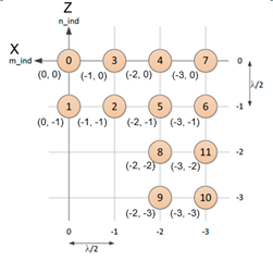
I compared the different between these two virtual antenna coordinates, and can understand m_ind, n_ind, phase rotation. We first get "element spatial locations" from m_ind and n_ind, then can create steering vector.
But what I am confusing about is the Guide saying "only azimuth-antennas, 8 antennas of the pre-calculated azimuth steering vectors are used."
Q1: For ODS pattern, how many or which antennas should I use when do the azimuth angle estimation?
And, when estimating the elevation angle, the Guide saying "all 12 antennas are used. The elevation steering vectors are calculated by multiplying pre-calculated elevation steering vectors with the azimuth steering vector corresponding to the detected point." I followed the step of '6.1.1.1.1.1 Azimuth steering vectors calculation' and '6.1.1.1.1.2 Elevation steering vectors calculation', and get steeringVecAzim shape (187, 12), steeringVecElev (187, 12), correspondingly.
(azimuth steering vectors include phase rotation coefficients, but elevation steering vectors not).
using parameters:
ANGLE_RES = 0.75
ANGLE_RANGE = 70
ANGLE_BINS = int((ANGLE_RANGE * 2) // ANGLE_RES) + 1
Q2: My question here is what's the meaning of multiplying two steeringVec together? Why not just select the elevation direction antennas?
It would be of great help if TI could provide example code for the signal processing chain. Or where can I find more information on these. Any help is greatly appreciated.
Thank you,
Shuting