This thread has been locked.

If you have a related question, please click the "Ask a related question" button in the top right corner. The newly created question will be automatically linked to this question.

TDC7200EVM: Unable to write to device

Part Number: TDC7200EVM
Other Parts Discussed in Thread: MSP-EXP430F5529LP, TDC7200, TDC7201

Hi guys,

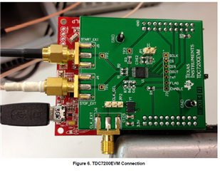
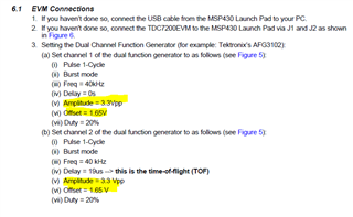
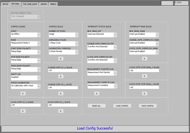
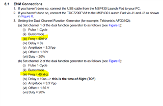
I'm using the TDC7200EVM with the MSP430 Launch Pad (MSP-EXP430F5529LP). I'm attempting to configure the options in the GUI to match those found in the manual.
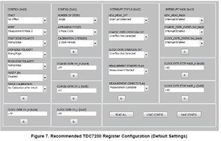
However,

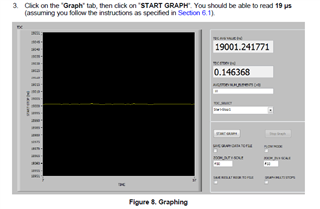
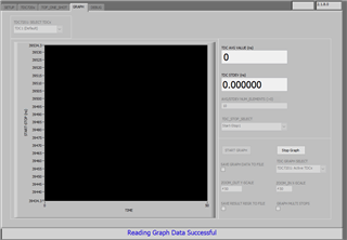
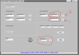
When I attempt to change any of these values and click the read all button (or any read button) I see that the value actually hasn't changed (I get the original value returned). I also attempted to write directly to registers 0x00-0x07 using the Debug Tab. Steps 1 & 2 below resulted in me reading the original value of xFF, where I attempted to write 0x02. I did manager to update the firmware as shown.

Is there something I'm missing? I'd like to change the registers in order to configure a test using the GUI.

Thanks,

Chris

  • Hey Chris,

    The EVM appears to be properly communicating with the computer since you were able to update the firmware and your screenshots show the connection.  

    If you toggle the "LINK LED" on the bottom of the DEBUG page, does a light go on and off on your board?  Similarly, if you go to the graph tab and click start graph does anything show up or does it give us any other useful errors?  

    Do you have a function generator hooked up to the board's START/STOP connectors?  I wouldn't think that this would stop the EVM from even changing register settings, but worth checking/trying.  Also make sure Jumper JP2 is connected between pins 2 and 3 so it's using Y1 as the CLOCK source.  

    You can also try clicking the "RESET TDC720x" button on the GUI (debug tab) to see if that helps anything. 

    Regards,

    Jacob

  • Hi Jacob,

    thanks for your quick follow up. I have a delay generator set up on the TDC, its configured matching the test procedure shown in the GUI's manual. With the exception of the amplitude, I have both channels set to 2Vpp (Due to a limitation of the Delay Generator).

    From Manual

    Actual Output I see on the GUI.

    Previously,

    before programming the device with the firmware included with the GUI the graph would error out after timing out following pressing the start button. Here I see the indication that graph data is being read successfully.

    I'll follow up later this afternoon when I arrive at the lab and try testing the LED and reset buttons.

  • Hi Jacob,

    I found that the TDC7200 was plugged into the LaunchPad incorrectly, it was reversed. After replacing the TDC board I'm not able to write to it, however I'm still unable to read any information from the Graph on the GUI Tab.

    I recently verified my start/stop delays using an oscilloscope, and now wondering if it could be related to my configure in the GUI.

  • Hey Chris,

    Ahh good to hear, that's progress. 

    Just to make sure, did you put a jumper on JP1 to give the device VCC via MSP430 power?  

    Another thing to check - try wiggling the TDC7200 up ~1mm from the MSP board.  I can't locate a TDC7200EVM, but with my TDC7201EVM there's a problem where if you push the board all the way down one of the connector headers shorts to a jumper on the board and causes connection issues with the computer.  Lifting it up a little fixed it. 

    When I click "READ ALL" on the debug page it can read all the registers, does that work for you?  Just trying to make sure all your connection/control things work before moving onto the device settings.  Your GUI configuration in the screenshot looks correct to me.  

    Regards,

    Jacob

  • Thanks Jacob,

    yes the jumper was set for JP1 following the example in the user guide.

    Regarding your advice about plugging in the TDC board, is this an issue with all boards connected to the launchpad? Or is this specific to the TDC board?

    I'm also able to read all registers on the debug page.

    Lastly, I did notice a problem when I followed the example in the TDC board user guide. The rate suggested by the example (40kHz) for the delay generator resulted in a glitch. I observed the start/stop pulses on an oscilloscope and see a third pulse which nearly overlaps the start pulse. It appears to be related to the recommended settings for delay/frequency; the delay being 19us and the period being 25us.

    Lastly, an unrelated topic. I'm looking at testing another shield with the launchpad. The RS485 Click 5V. I'm looking for an existing project I can leverage in order to perform UART communication over the mikrobus of the Launchpad. Can you point me in the right direction where to ask this question?

  • Hey Chris,

    Could you post an oscilloscope pic of the third pulse you're seeing?  Does it look like another start pulse?  Maybe try different settings, I agree it sounds suspicious with the delay being shorter than the period so maybe it's sending another pulse in the middle of the delay for the first pulse.  We're working on getting our hands on a TDC7200 ourselves to help test with.  

    On your 40kHz glitch, try another frequency if you want, 40kHz isn't a requirement just a suggestion to get started.  Maybe another frequency won't have this issue.  

    Regarding your advice about plugging in the TDC board, is this an issue with all boards connected to the launchpad? Or is this specific to the TDC board?

    Just an issue with this TDC board (specifically the TDC7201 but maybe 7200 as well) due to our placement of some headers 

    Could it be possible you damaged the TDC7200 chip on the EVM at some point and that's why it isn't responding?  It might be worth the time to swap it out for a fresh device just to rule that out if you think your function generator settings were ever at dangerous levels for the chip.  

    On the UART module - the sensing EVMs don't use UART, but I know that Motor Drivers EVMs do.  Download the firmware files for an EVM (DRV8462EVM for example, Download options, download the
    DRV84XX-DRV89X2-DRV82X2-EVM-SOFTWARE.zip, go into "DRV84xx_DRV82x2_DRV89x2_EVM_Firmware_v0.24.zip" and look at uart.c and uart.h, and Serial_Cmd_Monitor.c/h. ).  FYI the motor drives EVMs are based on the MSP430F5338, which is different than the MSP430F5529 on the launchpad.  This is a common launchpad, so a google search about using it with UART turns up some helpful examples - link1 link2 and lots of E2E posts with specific problems.  

    If you're talking about MikroBus specifically, maybe this post could help?  https://e2e.ti.com/blogs_/archives/b/designproject/posts/mikro-elektronika-39-s-7-segment-quot-click-board-quot-with-msp430-launchpad-and-energia  The correct E2E group for more questions on this would probably be the MSP low-power microcontroller forum (link)

    Regards,

    Jacob