This thread has been locked.

If you have a related question, please click the "Ask a related question" button in the top right corner. The newly created question will be automatically linked to this question.

LDC1312EVM: Using the LDC1312EVM and LDCCOILEVM

Part Number: LDC1312EVM
Other Parts Discussed in Thread: LDCCOILEVM, LDC1312

We have purchased the LDC1312EVM and set it up so one of the channels is connected to a LDCCOILEVM example coil. The coil chosen is coil C (100 x 8mm, 17 turns, 4mil trace, 4mil space, 5.69mm loop stepping, 2 layers). 

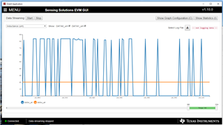
When using the coil the on LDC1312EVM (channel 1) the Sensing Solution GUI can successfully stream data showing the change in the inductance as a magnet is moved along it. However the coil C that is setup on the other channel cannot stream data. It is measuring changing in the inductance when there is nothing close it it and cannot smoothly pick up on the movement along the coil. 

The capacitor placed on the example coil is 100nF at C_C. Should this be adjusted and it so what calculation is recommended to get the best value capacitor?
  • Catherine,

    If possible, please look at the sensor waveform on a oscope with a high impedance probe.
    It sometimes helps to put a 1k resistor on the tip of the oscope probe and use the other end of the resistor as the probe tip.

    The sensor waveform should stay within the recommended LDC1312 limits of 10kHz to 10MHz.
    If it is not, then the C_C will need to be adjusted to bring the sensor frequency within the recommended range.

    There are two approaches.
    The first sort of hardware-based trial-and-error: use the coil C data in the LDC Reference Coils User’s Guide with the familiar LC resonant equations to calculate a C_C to bring the sensor frequency within the recommended range. As you sweep a conductive target over the coil, it will reduce the coil's inductance and make the sensor frequency shift up.
    For this reason, it may be best to pick C_C to bring the sensor frequency (w/o the target) into the lower half of the sensor's frequency range.

    The other approach uses the Excel-based  Inductive Sensing Design Calculator Tool that can be downloaded from ti.com.
    You can enter the parameters for the C_C and the coil C in the the Spiral_Inductor_Designer tab and the tool will estimate the sensor behavior for varying target distances.
    It will give a warning if the sensor frequency is too high or two low.  Be sure to select LDC1312 in the LDC Device field. You can find a potential solution with a little trial-and-error and then dial in the design on hardware.

    We have some other resources that may help. 
    Please take a look at the [FAQ] Inductive sensing FAQ - Frequently asked questions for additional inductive sensing collateral and answers to frequently asked questions.
    Our Inductive Sensing Blogs give brief, concise posts to a variety of subjects on inductive sensing, including the use the design calculator tool.

    I hope this helps. Please let me know if you have any more questions.

    Regards,
    John

  • Is the 'Inductive Sensing Design Calculator Tool' still appropriate for the long rectangular asymmetric coils? 

    I cannot adjust the tool to work for a rectangular coil, only a circular or racetrack coils. Would the results be the same for the either coil?

  • Catherine,

    The Inductive Sensing Design Calculator Tool supports only circular and racetrack spiral coils.

    As a work-around, it might be worth consulting our LDCCOILEVM and its user's guide which has some rectangular coils with accompanying data. 
    Hopefully they have something close to what you need. 

    Regards,
    John