This thread has been locked.

If you have a related question, please click the "Ask a related question" button in the top right corner. The newly created question will be automatically linked to this question.

IWR6843AOPEVM: Hardware triggering: SYNC_IN pulse requirements

Part Number: IWR6843AOPEVM
Other Parts Discussed in Thread: IWR6843AOP, IWRL6432,

I have a couple of questions regarding hardware triggering. Note, SDK 3.5 Rev F.

Following the below documentation I've assured the trigger is high for >25 ns and <1us. On the scope it goes from 215ns to 414ns.
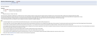
Does it really need to be less than 1us? I've ran the sensor with trigger signals > and < 1us and can't see a difference. This is of interest because 1us is a relatively strict requirement to fulfill and I can't see why it should need to be so small for a 10Hz measurement.

  • Hi Morten,

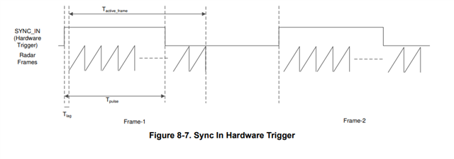
    The timing characteristics of hardware triggering is given below, kindly check if the default active frame time is 1us in SDK 3.5.

    Regards

    Ankit

  • What file is this found in?


    Also you say max is either T_active_frame or 4000ns. AFAIK active frame is chirp duration * number of chirps, lets say that is 6ms. For 3 Tx in TDM-MIMO that is 18ms. This is a wildly different number than 4000ns, which is relevant here?

    The more important question is maybe what happens if the pulse is too long? Are we worried that it'll cross over such that one really long pulse will trigger the sensor to chirp twice? Or are there other implications

  • Hi Morten,

    The maximum triggering time less than the active frame duration is relevant here. I need to check with the SDK team regarding the given constraint of 1us maximum time given in the SDK3.5 documentation.

    Regards

    Ankit

  • Ah okay, this is the PRI no? If that is the case PRI for the chirp I had in mind is ~100us.

    I'm very interested to here how much of a problem this is, because I've run this with pulse widths in the single digit milliseconds, with no visible adverse effects. And this should most certainly be greater.

    You didn't mention in which document you had found these figures. Would you be able to share this with me, I've looked for similar specifications but all I could find from the SDK is what I put in the original post.

  • You can find the data in IWRL6432 datasheet. The exact triggering timing constraint may differ for IWR6843AOP from IWRL6432 but the basic concept of it being less than the active frame duration will be same. 

    IWRL6432 data sheet, product information and support | TI.com

    Regards

    Ankit

  • Hi

    I am also trying to perform the Hardware triggering with the SYNC_IN using the IWR6843AOPEVM, but I am struggling to even make it work.

    Can you share some more details about how you perform this feature?

    Many thanks!

    Best regards,
    Po-Chih chen

  • Did you manage to check with the SDK team? Still curious to hear your thoughts on

    Ah okay, this is the PRI no? If that is the case PRI for the chirp I had in mind is ~100us.

    I'm very interested to here how much of a problem this is, because I've run this with pulse widths in the single digit milliseconds, with no visible adverse effects. And this should most certainly be greater.

  • Hi Morten,

    Can you be specific what you meant by PRI.

    Regards

    Ankit

  • I don't exactly remember what it stands for, I had this question in another post.

    But it's terminology used in the ROS driver distributed by TI, so I just figured it was something you used internally. It's calculated in ParameterParser.cpp, I copied the calculation here:

    float PRI = (idleTime + rampEndTime) * 1e-6;
  • Hi Morten,

    The SYNC_IN pulse width can be increased from 1us to 4us in SDK3.5. It is a design requirement to support device functionality; keeping the width greater than 4us can lead to errors.

    I also checked with the SDK team, who couldn't figure out what PRI was, but from the stated calculation, it appears to be chirp cycle time. It has nothing to do with the SYNC_IN pulse width, and to be clear, 4us is not the PRI.

    Regards

    Ankit

  • Hi again,

    Thought I remembered figure out the PRI thing previously, turns out it stands for "Pulse repetition interval" according to this. But yes the same as chirp cycle time.


    The SYNC_IN pulse width can be increased from 1us to 4us in SDK3.5. It is a design requirement to support device functionality; keeping the width greater than 4us can lead to errors.


    This is very confusing. You previously said that the HIGH time should be less than the T_active_frame:

    where T_active_frame is given by


    As we both came to understand, the PRI reported by the ROS driver is the chirp cycle time. Therefore T_active_frame = chirp_cycle_time * number_of_chirps.

    T_active_frame can very easily, and very likely cross into ms given the config parameters. Even the default config in the TI sensing estimator has a idleTime and rampEndTime such that a single chirp takes >50us.


    The information you've provided so far feels relatively contradictory, please advise.

  • Hi, 

    I want to clarify that there is an or between the 4us and the active frame time. Whichever is less must be satisfied (minimum of the two must be considered).

    Regards

    Ankit

  • The confusing part for me is it seems like having a T_active_frame < 4us is virtually impossible for this sensor?

    But okay, if it's the minimum then the previous question is at least cleared up.

  • Hi, for IWR6843AOP you can follow what has been mentioned at 1us, for IWRL6432 you can have minimum of active frame time or 4us.