Because of the holidays, TI E2E™ design support forum responses will be delayed from Dec. 25 through Jan. 2. Thank you for your patience.

This thread has been locked.

If you have a related question, please click the "Ask a related question" button in the top right corner. The newly created question will be automatically linked to this question.

[FAQ] What are the benefits and SW migration effort moving to AWR2944 from AWR1642/AWR1843?

Part Number: AWR2944
Other Parts Discussed in Thread: AWR6843, AWR1642, AWR1843, AWR2243

<-- Refer mmWave Sensor FAQ

If you are already working on AWR1642/AWR1843/AWR6843 (1st gen) mmWave sensor device and wondering if to move to the AWR2944 (2nd Gen) mmWave Sensor then read further.

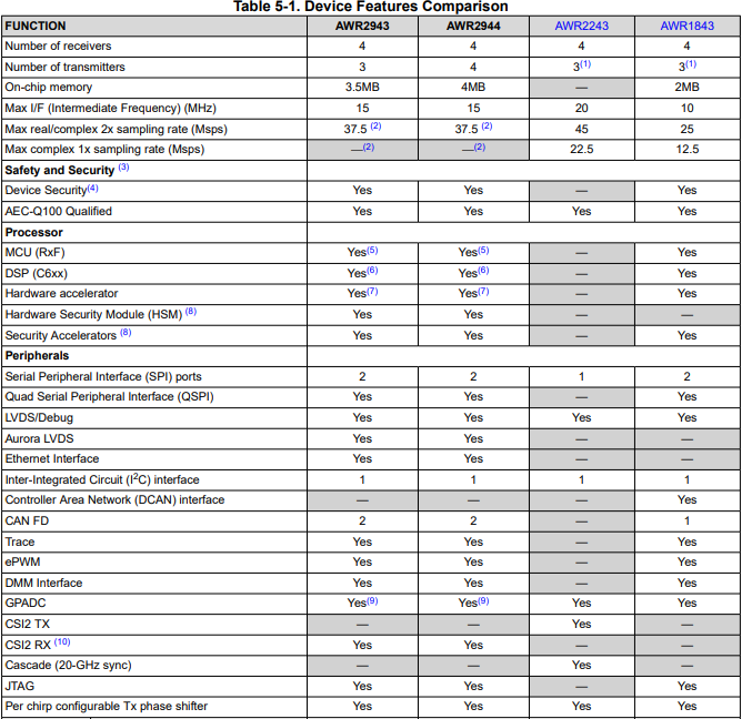
Here is high level feature difference b/w 1st Gen and 2nd Gen mmwave Sensor (from Datasheet)
Features AWR2944 AWR2243 AWR1843 AWR1642
Max Range(m)* 180-200

200-250 (single chip)

350+ (4xAWR2243 cascade)

120-150 60-80

Beam forming/Steering

(using Tx Phase Shifter)

Yes

Yes

Yes No
Usecase

Corner Radar,

Front Radar,

ACC, AEB, FCW

Front Radar,

Corner Radar

ACC(Adaptive Cruise Control)

AEB (automated emergency Braking)

AES (Autonomous Emergency Steering)

FCW(Forward Collision Warning)

ALC (Automtic Lane Change),

BSD (blind spot detection)

ACC, AEB, CTA (cross Traffic Alert), Parking,

BSD, Parking, ALC, CTA

NOTE: selection of mmWave Sensor is purely depends on your usecase and it's range/velocity/accuracy specification. Above range data based on TI EVM, device chirp/profile configuration and can be further improved using high gain antenna and processing chain. Refer this appNote to understand about object vs range https://www.ti.com/lit/an/swra593a/swra593a.pdf 

Here usecase is small subset of all possible usecase with those devices, but user can extend that possibility with their application implementation.

  • Q: I'm using AWR1843 and now planning to move to AWR2944, what are benefit and migration steps to move my software to AWR2944?

    Please find below high level of SW migration guide from 1st Gen mmWave Sensor (AWR1642/AWR1843) to 2nd Gen mmWave Sensor (AWR294x).


    System config changes in AWR 2nd generation from 1st generation devices


             There are significant improvements in terms of the system configuration used for 2nd generation of AWR devices like AWR2944. First the system as a whole got updated with HWA2.1/2.0 in 2nd gen AWR devices (HWA 2.0 is used in AM273x processor and AWR2944 ES1.0 while AWR2944 ES2.0 has HWA2.1 version). HWA2.0/2.1 in 2nd gen AWR devices runs at 300MHz, a local maxima engine, better interference detection and mitigation capabilities, better CFAR engine, better FFT engine over HWA1.1 (which runs at 200MHz) in 1st gen AWR devices (like AWR1843). Also, the DSP used in 2nd gen AWR devices c66x DSP  over c674x DSP  in 1st gen AWR devices provides lot more performance improvement based on compute, parallelization, performance etc. 


             With these improvements, the 2nd generation of AWR devices can implement better algorithms like DDMA (Doppler Division Multiple Access) for covering R79 NCAP regulations which can detect cars up to 220m and bikes up to 170m in comparison with 1st generation devices. There are significant changes in the signal processing chain to achieve the DDMA chain implementation. One of the major improvements was the use of HWA2.x effectively with minimum DSP intervention and parallelism between HWA and DSP to achieve the same.


             The major change while porting from 1st generation to 2nd generation AWR devices is that in the 1st generation of devices it has ADCBuf memory mapped to HWA input memory (where EDMA transfer is not required after chirp ADC data is available), however in the 2nd generation devices, this feature is not available and EDMA transfer is needed based on ADC capture complete interrupt (though this transfer time can be in parallel to HWA processing).  Other changes while porting from 1st generation to 2nd generation of AWR devices could be in terms of software where there are few API changes for the HWA and EDMA drivers.


    OOB (Out of box demo) Signal processing chain change

             The signal processing chain has changed a quite lot from 1st gen AWR devices to the 2nd generation AWR devices. Unlike the 1st generation devices which have the TDM-MIMO chain wherein only 1-Tx chirps at a single time instant, the 2nd generation AWR devices have all the 4-Tx chirping at the same time with a phase shift. This is achieved with a unique cyclic phase sequence using the TX phase shifters. As simultaneous Tx transmit, higher SNR is achieved when compared to TDM-MIMO chain in 1st generation AWR devices with easy Vmax extension for 2nd generation devices.                 

             As mentioned previously, the 2nd generation of AWR devices have the capability to perform the signal processing operations utilizing HWA2.x alone which will be faster and reducing the load on c66x DSP. Hence in 2nd generation, we have used only HWA for signal processing operations.

              As the DDMA (Doppler Division Multiple Access) signal chain (in 2nd generation devices) needs more data (more chirps/ADC samples) to get the required performance, there is a need for additional step of compression after range-FFT and decompression before Doppler FFT. In the range processing, additional steps of DC estimation and subtraction (due to DC removal block in 2nd gen over 1st gen), interference detection and mitigation (this block is enhanced from the 1st generation due to I-only architecture of 2nd generation devices), and finally the compressed radar cube (after 1D-FFT) is stored in the L3 memory. Range processing block uses HWA and EDMA alone with no intervention of DSP.

             Before the Doppler processing, this compressed radar cube must be decompressed and then only 2D-FFT has to be applied. In this Doppler processing step, detection matrix, DDMA metric etc are calculated. Based on this, doppler demodulation is done which can help us figure out for an object which virtual antenna does it correspond for angle estimation step. This step of DDMA demodulation is done in DSP while the HWA does the steps of Doppler processing. Followed by this Azimuth FFT is done, then CFAR-OS in Doppler direction on Azimuth samples. The local maxima engine of HWA2x is leverage to perform local maxima on Azimuth samples in both range and doppler dimension. The intersection of peaks of local maxima and CFAR is taken as detected objects. This process of extracting object list is done by DSP while in parallel HWA might be performing Doppler/Azimuth stage. In addition to this, there is the range CFAR DPU (which is optional), which performs CFAR from detection matrix. If the range CFAR DPU is enabled then for estimation of point cloud information x, y and z, this has to be the intersection of peaks from Doppler-Azimuth DPU and range CFAR DPU else Doppler Azimuth DPU alone is used.


             Higher SNR and Doppler ambiguity removal (through empty band) makes the DDMA modulation scheme more robust than traditional TDM chain in 1st generation devices.


    TDM-MIMO (1st generation AWR devices)

    DDM-MIMO (2nd generation AWR devices)

    Perfect orthogonality across Tx channel. Reduced instantaneous transmit power.

    Good orthogonality across Tx channel. All the Tx transmit at the same time with phase shift. High transmit power.

    Lower SNR when compared to DDM

    Higher SNR by 10*log10(Ntx) when compared to TDM

    Easy implementation from software perspective

    Software implementation is complicated than TDM

    Reduced max velocity. Vmax recovery requires more computation

    Easy Vmax extension

    Lower power consumption

    More power consumption

    Used for applications for low Vmax and short range

    Used for applications of high Vmax and long range


    HWA2.x key features over HWA 1.1

             The HWA2.x has the key feature of context-switching which allows user to switch to range processing operations in middle of doppler or azimuth processing chain operation when the trigger for next chirp available comes due to lesser frame idle time by the use of thread switching. The HWA2.0/2.1 can run two threads namely the high priority thread (context-switch state) and low-priority thread (default running state of HWA). This enables the user for more unique chirping schemes.

             The HWA2.0/2.1 supports 10-complex multiplication modes (with features as recursive windowing, frequency shifter with fine frequency increment), zero-insertion (filling of zeros at arbitrary locations - different from zero padding), channel combination etc


             In addition to this, HWA2.0/2.1 supports 3*2^N FFT, direct 2D-FFT computation and also advanced statistics block for local maxima and CFAR computation. The table in next page shows the key feature enhancements of HWA2.0/2.1 over HWA1.1 in 1st generation devices.


    HWA 1.1

    HWA 2.1/2.0

    Operating Clock

    200MHz

    300MHz

    Local RAM

    16KB x 4 = 64KB

    16KB x 8 = 128KB

    Max FFT size

    1024 (2^N FFT)

    2048 (2^N) and 1536 (3*2^N)

    Parameter-Sets

    16

    64

    Interference statistics

    Interference zero-out based on threshold

    Interference zero-out/interpolation/ window

    DC correction/estimation

    -

    DC estimation/correction

    CFAR modes

    CFAR-CA

    CFAR-CA, CFAR-OS

    ACCEL-Mode

    FFT, Compression, CFAR

    FFT, Compression, CFAR, Local-Max

    Statistics

    1D sum, 1D max

    1D sum, 1D max, histogram, CDF, 2D max


    Performance comparison between C66x DSP and C674x DSP

             On the C66x ISA, the vector processing capability is improved by extending the width of the SIMD instructions. The C674x DSP supports 2-way SIMD operations for 16-bit data and 4-way SIMD operations for 8-bit data. C66x enhances these capabilities with the addition of SIMD instructions for 32-bit data allowing operation on 128-bit vectors.


    C674x

    C66x

    Fixed point 16 x 16 MACs per cycle

    8

    32

    Fixed point 32 x 32 MACs per cycle

    2

    8

    Floating point single precision MACs per cycle

    2

    8

    Arithmetic floating-point operations per cycle

    6

    16

    Load/store width

    2 x 64 bit

    2 x 64-bit

    Vector size (SIMD capability)

    32-bit

    (2 x 16-bits, 4 x 8-bits)

    128-bit

    (4 x 8-bits, 4 x 16-bits, 4 x 32-bits)


    References:

    1. Technical reference manual (HWA v2.x)of AWR294x (link)
    2. Radar Hardware Accelerator (HWA v1.1) user-guide (link)
    3. mmWave MCU Plus SDK documentation (link)
    4. TMS320C66X DSP CPU and instruction set (link)