This thread has been locked.

If you have a related question, please click the "Ask a related question" button in the top right corner. The newly created question will be automatically linked to this question.

IWRL6432BOOST: Processing and syncing raw ADC data with sideband info, captured without mmwave studio

Part Number: IWRL6432BOOST
Other Parts Discussed in Thread: MMWAVE-L-SDK

Hi,

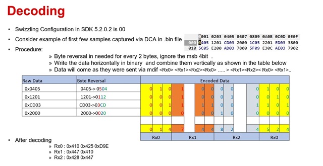
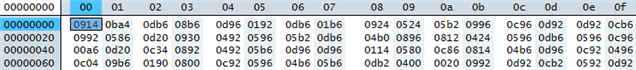
I am trying to do some post-processing on raw ADC data captured using the DCA1000 without the use of mmwave studio, i.e. the data capture was done using the mmwave demo SW with SDK 5.02.00.02.

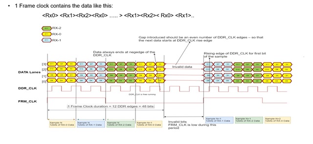
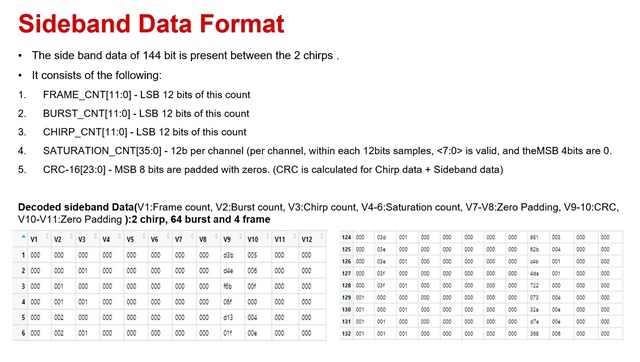
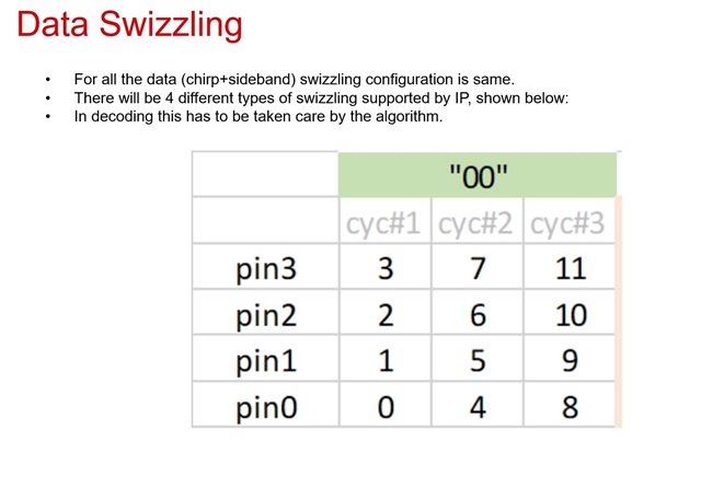
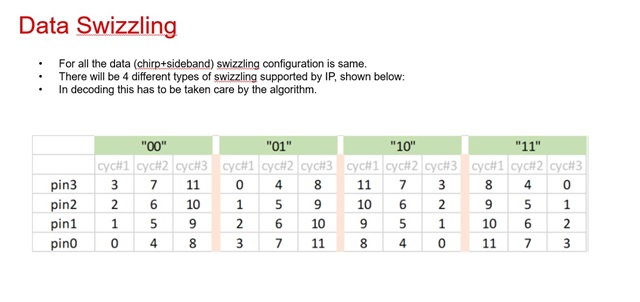
Previously, when we had done captures with the DCA and mmwave studio (with sideband data disabled) we were able to extract the relevant data from the raw capture without issue. Now, when enabling ADC logging in the mmwave demo SW, with sideband data enabled, which if I am not mistaken, appends 96 bits of data to the end of the chirp data. Am I correct in thinking that this would cause a syncing issue that would need to be accounted for in post-processing? (in addition to the usual syncing issue that could occur due to not using mmwave studio i.e. the radar begins transmission before the DCA begins capturing)

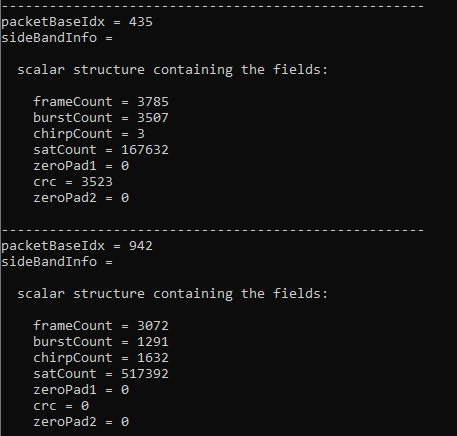
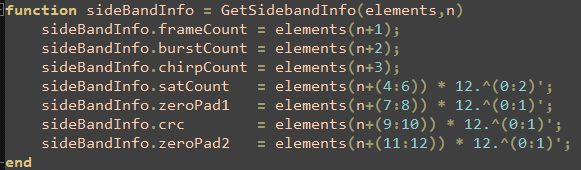
In a previous forum post here: https://e2e.ti.com/support/sensors-group/sensors/f/sensors-forum/1232378/iwrl6432boost-enabling-data-streaming-via-ldvs-in-software, it was mentioned that the sideband data can help to sync the ADC data. In this case how should we go about using the sideband data to do this? Do you have any existing tools that can help us to sync and read in raw ADC data with sideband info enabled?

Best Regards,

Yohennas Folly

  • Hello Yohennas,

    Sideband data in MDIF contains frame number, chirp number and saturation count. As DCA1000 inserts some data in-between the capture, once sideband data is decoded in the capture then chirp data can be extracted correctly. You can use this to know what frame you are on. MMWAVE-L-SDK raw data log sends out this MDIFdata with sideband data. As far as tools and examples go, I will need to look into this more.

    Best Regards,

    Pedrhom

  • Hi Yohennas,

    We have a r script which decodes the data collected in DCA1000 while running the SDK 5.2. The script takes the .cfg file as the input along with the log collected in DCA1000. The script allows you to select the frame/burst/chirp and displays the data for the selected chirp

    #MDIF Chirp data and sideband data
    #!/usr/bin/env Rscript

    rm(list = ls())
    folder_name = "C:/d_drive/lpradar/mdif/mdif_data_decoder_sdk_5_2/"
    t<-readLines(paste0(folder_name,"MotionDetect_mdif.cfg"), n=12)

    N_samples = as.integer(strsplit(t[9], split = " ")[[1]][5])
    N_chirps =as.integer(strsplit(t[11], split = " ")[[1]][2])
    N_brusts=as.integer(strsplit(t[11], split = " ")[[1]][5])
    N_frames=as.integer(strsplit(t[11], split = " ")[[1]][7])

    N_rx = 3
    max_frame=128
    side_band_EN=1
    if (N_frames)
    {
    N_frames=N_frames
    } else {N_frames = max_frame}

    chirp1=N_chirps*N_brusts
    chirps=N_frames*N_chirps*N_brusts
    total_samples_per_rx = N_samples * chirps

    N_bits = 12

    total_samples = total_samples_per_rx * N_rx
    total_samples_per_chrip = N_samples * N_rx
    x=as.integer(total_samples/728)

    #input <- readBin(paste0(folder_name,"mdif_capture_25_Raw_0.bin"), what = integer(), n = total_samples + 3*x+3, size = 2)
    input <- readBin(paste0(folder_name,"mdif_capture_sdk_5_2_Raw_0.bin"), what = integer(), n = total_samples + 3*x+3, size = 2)

    input = input[4:(total_samples +3*x +3)]
    input3 = array(0,total_samples)
    for (m in 1:x)
    {
    input3[(1+728*(m-1)):(728*m)]= input[(1+(731*(m-1))):((731*m)-3)]
    }

    r=dim(input3)/(N_chirps*N_brusts*(N_samples*N_rx+12))
    temp_array = array(c(0, 0, 0, 0))

    max_val = 2 ^ N_bits
    half_max_val = (max_val/2) - 1


    ######################Decoding###########################
    sideband_data = array(0, dim = c(chirps, N_bits))
    SideBand_data_hex = array(0, dim = c(chirps, N_bits))

    t=N_samples*chirp1*N_rx
    Frame_data=array(0, dim = c(N_frames, (t+12*chirp1)))
    chrip_data= array(0, dim = c(N_frames, chirp1, (N_samples*N_rx)))
    Chrip_data_out=array(0,N_samples)


    for (k in 1:N_frames)
    {
    Frame_data[k,]=input3[(1+(t+(12*chirp1))*(k-1)):((t+(12*chirp1))*k)]
    for (l in 1:chirp1)
    {
    if (side_band_EN)
    {
    chrip_data[k,l,]=Frame_data[k,(1+(l-1)*(N_samples*N_rx+12)):(l*(N_samples*N_rx)+12*(l-1))]
    }
    else
    chrip_data[k,l,]=Frame_data[k,(1+(l-1)*(N_samples*N_rx)):(l*N_samples*N_rx)]
    }
    }

    ##########################sideband_data############################
    mdif_sideband <- function()
    {
    SideBand_data = array(0, dim = c((chirps-1), N_bits))
    SideBand_data_hex = array(0, dim = c((chirps-1), N_bits))
    temp_array = array(c(0, 0, 0, 0))
    rx_val = array(0, total_samples)
    for (k in 1:(chirps-1))
    {
    sideband_data[k,]=input3[(1+(k*N_samples*N_rx)+(12*(k-1))):((k*N_samples*N_rx)+12*k)]
    }

    for (s in 1:(chirps-1))
    {
    input1_2bytes = as.hexmode(sideband_data[s,])
    count1 = 0
    for (i in seq(1, N_bits, 4))
    {
    temp_array[1] = input1_2bytes[i]
    temp_array[2] = input1_2bytes[i+1]
    temp_array[3] = input1_2bytes[i+2]
    temp_array[4] = input1_2bytes[i+3]
    for (j in N_bits:1)
    {
    temp0 = bitwAnd(temp_array[1], 2^(j-1)) / 2^(j-1)
    temp1 = bitwAnd(temp_array[2], 2^(j-1)) / 2^(j-1)
    temp2 = bitwAnd(temp_array[3], 2^(j-1)) / 2^(j-1)
    temp3 = bitwAnd(temp_array[4], 2^(j-1)) / 2^(j-1)

    temp_val = as.hexmode((temp3 * 8) + (temp2 * 4) + (temp1 * 2) + temp0)
    count1 = count1 + 1

    rx_val[count1] = temp_val
    }
    }
    p=1
    for (i in seq(1, (N_bits * 3), 3))
    {
    temp_rx_val = (rx_val[i+2] * 256) + (rx_val[i+1] * 16) + rx_val[i]
    SideBand_data[s,p]= temp_rx_val
    p=p+1
    }
    SideBand_data_hex[s,]=format(as.hexmode(SideBand_data[s,]), width = 3)

    }
    return(SideBand_data_hex)
    }
    #############################chrip_data####################################
    mdif_chripdata <- function(chrip_data,f,r)
    {

    temp_array = array(c(0, 0, 0, 0))

    max_val = 2 ^ N_bits
    half_max_val = (max_val/2) - 1

    rx_data = array(0, dim = c(N_rx, N_samples))
    rx_data_hex = array(0, dim = c(N_rx, N_samples))
    rx_val = array(0, total_samples)

    input_2bytes = array(0, total_samples)

    rx1 = array(0, N_samples)
    rx2 = array(0, N_samples)
    rx3 = array(0, N_samples)

    input_2bytes = as.hexmode(chrip_data)
    count = 0
    rx_count = 0

    for (i in seq(1, total_samples_per_chrip, 4))
    {
    temp_array[1] = input_2bytes[i]
    temp_array[2] = input_2bytes[i+1]
    temp_array[3] = input_2bytes[i+2]
    temp_array[4] = input_2bytes[i+3]

    for (j in N_bits:1)
    {
    temp0 = bitwAnd(temp_array[1], 2^(j-1)) / 2^(j-1)
    temp1 = bitwAnd(temp_array[2], 2^(j-1)) / 2^(j-1)
    temp2 = bitwAnd(temp_array[3], 2^(j-1)) / 2^(j-1)
    temp3 = bitwAnd(temp_array[4], 2^(j-1)) / 2^(j-1)
    temp_val = as.hexmode((temp3 * 8) + (temp2 * 4) + (temp1 * 2) + temp0)
    count = count + 1
    rx_val[count] = temp_val
    }
    }

    for (i in seq(1, (total_samples_per_chrip * 3), 3))
    {
    temp_rx_val = (rx_val[i+2] * 256) + (rx_val[i+1] * 16) + rx_val[i]

    rx_count = rx_count + 1

    row_num = rx_count %% 3

    if (row_num == 0)
    row_num = 3

    col_num = ceiling(rx_count / 3)
    rx_data[row_num, col_num] = temp_rx_val
    rx_dat_hex = as.hexmode(rx_data)
    }
    # for (i in 1:N_rx)
    # {
    # rx_data_hex[i,] = format(as.hexmode(rx_data[i,]), width = 4)
    # }
    rx1 = rx_data[1,]
    rx2 = rx_data[2,]
    rx3 = rx_data[3,]

    for (i in 1:N_samples)
    {
    if (rx1[i] > half_max_val)
    rx1[i] = rx1[i] - max_val

    if (rx2[i] > half_max_val)
    rx2[i] = rx2[i] - max_val

    if (rx3[i] > half_max_val)
    rx3[i] = rx3[i] - max_val
    }

    # plot_title_1 = paste0("FFT computed in R for Rx1 ", sprintf(" & Frame%d ",f))
    # plot(abs(fft(rx1)), type='l', main = plot_title_1)
    # plot_title_2 = paste0("FFT computed in R for Rx2 ", sprintf(" & Frame%d ",f))
    # plot(abs(fft(rx2)), type='l', main = plot_title_2)
    # plot_title_3 = paste0("FFT computed in R for Rx3 ", sprintf(" & Frame%d ",f))
    # plot(abs(fft(rx3)), type='l', main = plot_title_3)

    if (r==1)
    {return(rx1)}
    else if (r==2)
    {return(rx2)}
    else return(rx3)

    }

    ##############################User_Interface##########################################
    f = readline(prompt = "Plz Enter Frame number : ");
    f = as.integer(f)
    print(sprintf("CFG has %d burst",N_brusts))
    b = readline(prompt = "Enter Burst number : ");
    b = as.integer(b)
    print(sprintf("CFG has %d chirp",N_chirps))
    c = readline(prompt = "Enter Chirp number : ");
    c = as.integer(c)
    r = readline(prompt = "Device has 3 Rx,enter the Rx : ");
    r = as.integer(r)

    SideBand_data_hex=mdif_sideband()

    ###############################sideband_check#################################

    key=(f-1)*N_brusts*N_chirps + (b-1)*N_chirps + c
    if (SideBand_data_hex[key,1]==format(as.hexmode(f-1),width = 3) & SideBand_data_hex[key,2]==format(as.hexmode(b-1),width = 3) & SideBand_data_hex[key,3]==format(as.hexmode(c-1),width = 3))
    {
    k=(b-1)*N_chirps+c

    Chrip_data_out=mdif_chripdata(chrip_data[f,k,],f,r)
    Chrip_data_out=as.hexmode(bitwAnd(Chrip_data_out, 0xfff))
    #Chrip_data_out=format(as.hexmode(Chrip_data_out),width = 3)
    print(Chrip_data_out)
    } else
    {print("Sideband data is not correct")}

  • Hi, 

    Below is some explanation for the decoding

  • Hi Abishek,

    Thanks for the detailed response. I will let you know when we manage to get the data processed.

    I was also wondering if there is anyway to resync the raw data if for instance capturing only began in the middle of a frame? Is there some kind of magic word or other method that can be used to find the start of a new frame?

  • Hi,

    With the current frame rate of 4 frames a second in the demo, even if you start the capture in the middle of the demo, you are likely to capture from the start of the frame as the overall duty cycle is very less. 

    If you increase the duty cycle, then you will have to search by frame number, burst number, chirp number in the sideband data. There is no magic word for synchronization

    Regards,

    Abhishek

  • Hi again Abhishek,

    We are still struggling to decode the raw ADC info and have a few questions:

    1. Does the junk data that is sometimes inserted into the capture occur when capturing with mmwave studio as well?
    2. How do we decode the data if data swizzling is set to a different mode? When we captured with mmwave studio previously, we used the PIN0_BIT0_CYL3 swizzle mode and had a matlab script that was able to decode this successfully, but now capturing with our modified demo SW in this same swizzling mode there seems to be issue with the decoding.
    3. Am I correct in saying that both the chirp data in and the sideband data are in the swizzled format?
    4. If this is the case, from the above image it seems as if swizzled data needs to be decoded in 4 16 bit sections, if there is junk data that is unpredictably added to the capture would this data not offset the decoding and cause all the data from that point to be incorrectly decoded?
  • Hi Yohennas,

    1. DCA1000 inserts 3 bytes of junk data for every 728 bytes. It happens in mmwavestudio also

    2.Data swizzling in mmwavestudio and SDK5.2.0.2 are different. They are 4 types of data swizzling possible. SDK 5.2.0.2 uses mode "00"

    3. Yes, Chirp data and sideband data are swizzled and both are swizzled in the same format

    4.Did you try with the r script that I mentioned above? After decoding the swizzling, if you are able to locate the side band data they you can easily extract the chirp data. When looking for the sideband data, do look out for increasing pattern of chirp numbers when the Frame numbers and burst numbers are constant

    Regards,

    Abhishek  

  • Hi Abhishek,

    I just want to check whether the swizzling method can be changed in the demo? We changed the swizzle mode to match that of mmwave studio as seen below:

    Is this supported?

    Also if the junk data is inserted in mmwave studio as well, does mmwave studio implement an additional step that gets rid of the junk data and allows for post-processing in matlab directly? It seems like in previous versions of mmwave studio Packet_Reorder_Zerofill.exe was used to clean up the data for post proc. Would the same thing need to happen with the raw radar data captured with the Demo code?

    Regarding the r script, we are still figuring out how to correct de-swizzle the data so have not been able to use it properly yet

  • Hi Yohennas,

    Yes, swizzling mode can be changed in the demo, you can select one of the 4 modes

    In the file common_full.c, ptrOpenCfg->fecRDIFCtrlCmd.c_RdifCfg = 1U

    Able line needs to be changed. 

    Yes, mmwavestudio removed the junk data while performing the post processing.

    Regards,

    Abhishek

  • Hi Abishek,

    I have been working on decoding the data while Yohennas is away.

    I started by looking at the decoding implementation, as described in the image you shared:

    I have implemented something that for the same input (0x0405 0x1201 0xCD03 0x2000) returns the same output (0x410 0x447 0x428 0x425). I have a few questions at this point.

    Question 1: Byte reversal.

    Here is the start of a file that we captured with sideband info enabled and swizzle mode 0, viewed in Hex Editor Neo with the data grouped by 16-bit words:

    This does not appear to require byte reversal, since the most significant hex digit of each word is zero, unlike your example where the third hex digit of each word was zero. Should I skip byte reversal for this data?

    Question 2: Sideband info

    Whether or not I perform byte reversal before decoding, I do not see the sideband data as I would expect in the decoded data. I wrote a script that looks for possible sideband data structures in the decoded data, i.e. where the two zero pad sections are zero, and then the other data does not look correct:

    Here is the code that reads sideband info from a given position in the list of 12-bit elements:

    Do you have any ideas as to why I'm not seeing the sideband info?

    Question 3: Test pattern

    We tried doing a capture with the test pattern enabled (ptrOpenCfg->fecRDIFCtrlCmd.c_TestPatternEn = M_RL_FECSS_TEST_PATRN_ENA), but we haven't been able to see the test pattern in the data. Can you confirm whether the test pattern is implemented in the SDK?

    Thanks in advance,

    Bertus

  • Hi Bertus,

    Byte reversal was only to demonstrate the formatting. As the editor we used was reversing the data, it was demonstrated that way.

    1.You need not perform byte reversal when reading the binary file. 

    2.Sideband data decoded does not seem correct.

    3.In SDK 5.2 test pattern is disabled.

    We have created a matlab script to decode. I am attaching it here along with the cfg file and the captured data using DCA1000

    We have observed that in some Windows PC's the ethernet packets received from DCA1000 are packed in a different way. 

    The reference capture should give you some inputs

    mdif_decode.m

    MotionDetect_mdif.cfg

    mdif_capture_sdk_5_2_Raw_0.bin

    Regards,

    Abhishek