This thread has been locked.

If you have a related question, please click the "Ask a related question" button in the top right corner. The newly created question will be automatically linked to this question.

TDC1000: Configuring TDC1000-C2000 EVM for transducer

Part Number: TDC1000
Other Parts Discussed in Thread: TUSS4470

Good Afternoon,

I am using a 3 MHz STEMINC Transducer (SMD25T07F3000WL) and I have it bottom mounted to a graduated cylinder for level sensing. Previously I was using a 1 MHz transducer but switched to 3Mhz in an effort to reduce beam spread, currently when I have it plugged in I am unable to get a reading. I was wondering what my configurations need to be changed to in the TDC1000 GUI application for this new transducer to function.

  • Hello Sahaj,

    Thank you for posting to the sensors forum,

    It is not possible to use a 3 MHz transducer using the onboard clock. The EVM uses an 8MHz clock, and the frequency divider only allows the TX frequency to be divided by multiples of 2, which means a 3MHz frequency is not possible with this configuration.

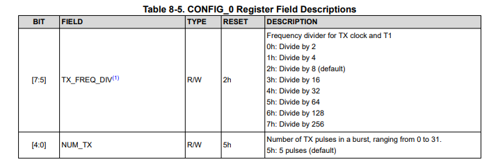
    If you want to use a 3 MHz transducer, you could instead use an external clock that would be connected through JP1 or through TP19. Keep in mind that the GUI must also be updated to use an external clock instead of the internal clock on the first page. Using an external clock, you then need to setup the CONFIG_0 register by selecting the frequency divider value that will support your 3 MHz transducer.

    If you wanted to continue to use the 1MHz transducer, you can also use a waveguide to reduce beam spread.

    Thank you,

    Daniel Balmaceda

  • Hi Daniel, thank you for your response. I was curious about the waveguide that you mentioned. Eventually this sensor would be submerged and has been submerged in previous testing but ran into the same beam spread issue. Is it possible to use a waveguide in the submerge scenario, if so do you have any resources that you recommend?

  • Hello Sahaj,

    Yes, it is possible to use a waveguide in this scenario. I do not have any additional resources, but I do have an example of a waveguide being used to reduce beam spread in an underwater case: 


    As you can see, the wave guide is just an additional tube that we have inside the tank. The reduced area keeps the wave in a concentrated space.

    Thank you,

    Daniel Balmaceda

  • Hi Daniel, thank you for the guidance. I connected waveform generator to TP19 and set the GUI to an external clock, I am using an 8Mhz frequency to make sure that I have setup the external clock correctly but the GUI is suggesting that I need to move a jumper to external clock. Is that necessary for this dev board? 

  • Hello Sahaj,

    Yes. in order to use your external clock, you will have to move the jumper on JP1 from EVM to EXT.

    Thank you,

    Daniel Balmaceda

  • I have moved the jumper over, and verified using an oscilloscope that I am putting 8Mhz on the external clock at TP19. I have adjusted the TDC_CLK_SOURCE_SELECT to external but am unable to get a reading using a 1Mhz transducer. As soon as I switch back to the internal clock (8Mhz) it works perfectly fine. Any suggestions as to what I am missing.

  • Hello Sahaj,

    Whenever you are setting up your external clock on your function generator, make sure that you are outputting a square wave with a 50% duty cycle. Additionally, make sure that the peak-to-peak voltage of the signal is at least 2.7V with a maximum of 5.5V, and make sure to offset the signal so that the low value is 0V. Here is an image of an example waveform used for the clock:

    For this example, I used a 8 MHz signal with a 3V peak-to-peak and an offset of 1.5V to ensure 0V to 3V operation.

    I hope this helps.

    Thank you,

    Daniel Balmaceda

  • Thank you, this helped me resolve my issue with the 8Mhz external clock signal, now that I know the external clock is working, I am trying to use it on a 3.4Mhz transducer. I set the external clock to 6.8Mhz and set that in the config as well. I set the TDC_FREQ_DIV to by 2 and am unable to see the signal graphing. Is there any special configuration that should be used for the 3.4 Mhz Transducer. Again apologies for all the questions.

  • Hello Sahaj,

    There are a couple of things that might cause an issue:

    1. Higher frequencies tend to attenuate faster, so you may need to increase your PGA_GAIN value

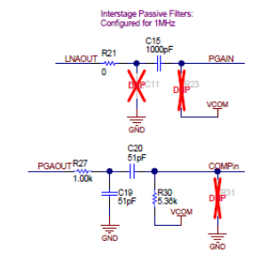
    2. The interstage filters on the EVM are configured for a 1MHz transducer. You may need to change the component values within these filters

    What application are you using the 3.4 MHz transducer for?

    Thank you,

    Daniel Balmaceda

  • I was hoping to use it in a level sensing application as I thought a higher frequency transducer would reduce beam spread. The answer you suggested above worked well, my issue is that the distance the sensor is able to read is only up to 8-10 inches. Do you have any recommendation for ultrasonic disc sensors that will work in a level sensing application that is 7ft-8ft as my testing has showed that the sensor could not produce a strong enough pulse to be registered after 10 inches. In the application I described the sensor would be bottom mounted.

  • Hello Sahaj,

    The beam spread is mainly associated with the transducer. Different manufacturers offer different FOV angles. There are a couple of other ways that you can increase the range for your application:

    1. Higher frequency signals attenuate faster, so a lower frequency transducer will carry more energy to help the signal travel further

    2. The tranducer's excitation voltage needs to be increased significantly to provide a larger signal that can achieve your 7ft-8ft requirement. The TDC1000 is only capable of generating a 5V excitation on the transducer, but we have a reference design that can help you achieve a larger distance. Here are a few resources that may help with this:

    https://www.ti.com/tool/TIDA-00322

    TIDU616.PDF

    This reference design uses additional circuitry that increases the excitation voltage. Additionally, it may be worth looking into using the TUSS4470 for this application, as it provides a larger range.

    Hope this helps.

    Thank you,

    Daniel Balmaceda