


Dear team,
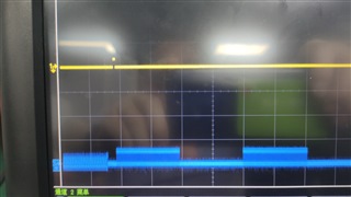
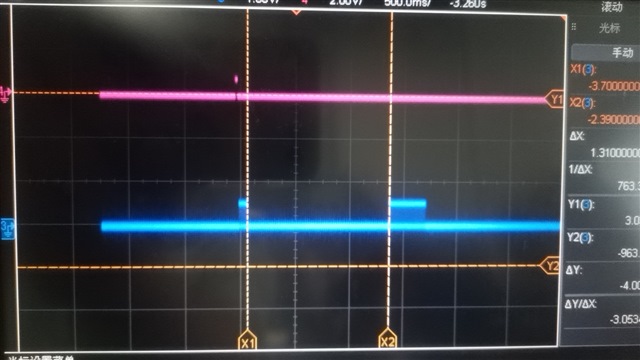
My customer is having trouble when using AFE3010. The alarm signal is kept turning on as blue channel. Yellow channel is SCR signal. The high level pulse width of yellow channel is 10ms。 The blue channel width is 1.2s.
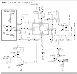
How did that happened? And how to remove the alarm signal? Is the schematic has any problem? Looking forward to your reply!


 '
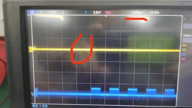
' This is the waveform of 2nd question with different pulse width of Alarm.
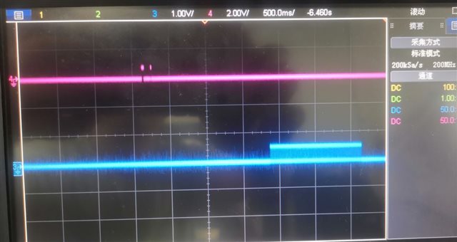 This is why occur twice SCR when detect leak current.