This thread has been locked.

If you have a related question, please click the "Ask a related question" button in the top right corner. The newly created question will be automatically linked to this question.

FDC2212: Configuring the sensor for high accuracy/precision, high speed applications

Part Number: FDC2212

Hi team,

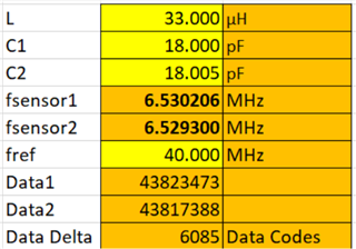
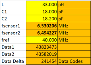
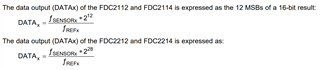
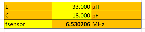
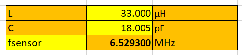
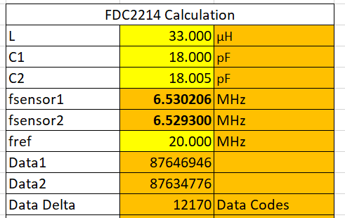
We are working on a capacitive sensing project that requires very high accuracy. Ideally, we would like the sensor to be able to differentiate in steps less than 5fF as our entire sensing range is roughly 200fF. Will the FDC 2212 be able to handle such precision and how should the LC resonator be configured in this case? I know that the typical configuration which works reasonably well in general is L=33uH and C=18pF, but I understand reducing C will yield a higher deltaC/C ratio and stray capacitances from the PCB or circuitry will reduce the sensor frequency. Furthermore, I think increasing the conversion time leads to higher resolution but we are trying to maximize our scan rate. Any suggestions are welcome!

Thanks,

Shane

  • Hello Shane,

    Thanks for posting on the forum!  We are looking into the details on this topic and will provide some recommendations by tomorrow EOD.

  • Shane,

    Please see the calculations below that show the expected ADC code delta with a 5fF change in capacitance.  I have also included the delta on the full 200fF range.  This does not take into account the noise floor which will be system dependent.  An increased RCOUNT value will provide better signal to noise ratio, but at the expense of longer time consumed.  RCOUNT should be set to provide the appropriate SNR and scan rate for your system.  When calculating the time, you need to take into account sensor activation time, conversion time, and channel switch delay.  Section 9.3.2 of the datasheet describes how to calculate each of these for your system.       

    5fF delta 

    200fF delta(full range)

  • Hi Eddie,

    Sorry for the late response. May I ask in what way does the data delta codes affect the data resolution? I'm trying to use this equation provided by the datasheet and solving for the ratio fsensor/fref as this is the output value of the CDC.

    I don't quite understand what the meaning is behind the magnitude of this ratio. I would like to relate that ratio (output of the CDC) somehow to resolution in femtofarads to understand the measured precision. Of course, the datasheet mentions that I can consider employing conversion data offset gain to increase my resolution by 4 extra bits to 16 bits. I'm having some trouble distinguishing the difference between resolution in terms of data delta codes, bits, and femtofarads. How can I accurately relate the number of data delta codes to a more tangible concept of resolution, like in femtofarads for instance if that makes sense?

  • Shane,

    I have attached the spreadsheet with formulas.  

    The cells below shows fsensor resonant frequency when there is no change in capacitance.  

    The cells below show fsensor after a 5fF change in capacitance.  

    We can then convert each frequency into the resulting data codes of the ADC using the formula you show.  Results are shown below.

    The data delta means that for every 5fF change, you will see a change of 12170 data codes using the 28 bit ADC of the FDC2212.  As mentioned before, this does not include additional noise floor from your environment.  Even with some additional noise floor, this should be sufficient for a 5fF step size.  LC Calculator for varying C.xlsx