This thread has been locked.

If you have a related question, please click the "Ask a related question" button in the top right corner. The newly created question will be automatically linked to this question.

PGA970: Phase detection with PGA970EVM board

Part Number: PGA970

Greetings,

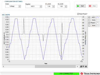
I am trying to use the PGA970EVM with a 4-wire RVDT sensor and I am unable to see a change in the phase angle (except for noise) when looking at the ADC capture from the provided GUI. I have tried numerous combinations of the GUI's ADC Interface controls to find success, but to no avail. I found this POST asking the same question (no posted solution) and I gather that the phase angle extraction feature should be working right out of the box.

I even tried a hooking up a second PGA970EVM kit but I am getting the exact same results on the ADC capture.

Please see the following attachments (hopefully they help):
- Screenshot of my ADC Capture plot from the GUI
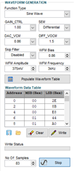
- GUI Configuration file
- PGA970 jumper configuration table
- PGA970 external hookup schematic
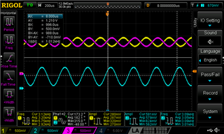
- Oscilloscope capture of my primary and secondary waveforms

Can you try my configuration file on your setup? Do you get the same result?

Could you send a configuration file that you are confident works so I could try it?

Are my jumpers in the right places?

Thank you!

Paul_Config.cfg

Jumper_Configuration.xlsx

  • Hi Paul,

    Welcome to the E2E forum!  Unfortunately I do not have a simulator nor a LVDT or RVDT sensor.  Some additional information would be helpful with respect to the operation of the sensor, such as operating voltage and frequency expected on the primary.  Have you enabled both ADCs to see if there are any differences?  You bypassed the amplifiers on the primary so without knowing more it would be difficult to say what might be happening relative to signal levels.  The phase is determined following the bandpass filter so it is at this point that phase is compared with the waveform generated signal. 

    As you can probably tell, the support for this device has been passed around a bit due to attrition. I understand the basics of this device, but I'm still learning the nuances of the GUI.  Our previous applications support team member was able to get this to work by using an external signal generator.  As this question has come up several times, I do believe it is a configuration issue so I will try get to the bottom of it.  I will review the configuration that you provided and get back to you as soon as I can, but most likely due to other activities I will not be able to give you much of an answer before Tuesday of next week.

    Best regards,

    Bob B

  • Thanks Bob!

    The power supply voltage to the chip is 12VDC. I posted a screenshot of my waveform generation settings in my reply. I think that answers your question with regards to the operating voltage and frequency, but let me know if it doesn't. My selected voltage/frequency aren't required for my application, it's just what I have been testing with.

    I have enabled both ADCs, however the result is the same. The phase angle reported in the ADC capture plot is always 45-deg, but looking at the oscilloscope image one can see that the phase difference is not 45-deg.

    You are correct that I am bypassing the external amplifier circuit. My application has no need for it.

    Looking forward to your reply next week.

  • Hi Paul,

    Thanks for the additional information.  I will get back to you next week as soon as I know more.

    Best regards,

    Bob B

  • Hi Paul,

    I'm learning a lot about this part and much of it is due to trial and error.  One thing that I discovered in your configuration are the settings for the phase measurements.  There are two measurements that are taken to determine the phase (two for each ADC channel). The values get set in registers DAC_SIN_NDS1_1 and DAC_SIN_NDS1_2 and there are an additional set for channel 2 (NDS2).  You have both set to the default value of '0'.

    The following information is taken from this E2E post:

    https://e2e.ti.com/support/sensors-group/sensors/f/sensors-forum/735209/pga970-detailed-description-of-registers-to-get-the-phase-information?tisearch=e2e-sitesearch&keymatch=pga970%252525252525252520phase

    The DAC_SIN_NDS1 and NDS2 are the registers you set to select where you will sample the DEMOD output. the PH1DATA is the demodulator output at the sample specified by DAC_SIN_NDS1, and the PH2DATA is the output at the sample specified by DAC_SIN_NDS2.

    The simplest way to use this is as follows:

    At DAC_SIN_NDS1 = 0, the DEMOD1_PH1DATA = A*sin(phase)

    At DAC_SIN_NDS2 = WAVEFORM_TABLE_LEN, the DEMOD1_PH2DATA = A*cos(phase)

    You can calculate the phase by taking the arctan of the two data points:

    phase = arctan(DEMOD1_PH1_DATA/DEMOD1_PH2_DATA)

    I hope the above information is helpful.  It is at least more clear than the datasheet discussion.

    Best regards,

    Bob B

  • Hi Bob,

    Thanks for the explanation. I hadn't seen that before but I understand better now. Thanks for your time and efforts!

    Kind Regards,

    Paul S