This thread has been locked.

If you have a related question, please click the "Ask a related question" button in the top right corner. The newly created question will be automatically linked to this question.

PGA900: PGA900 cannot operate when power is reapplied

Part Number: PGA900
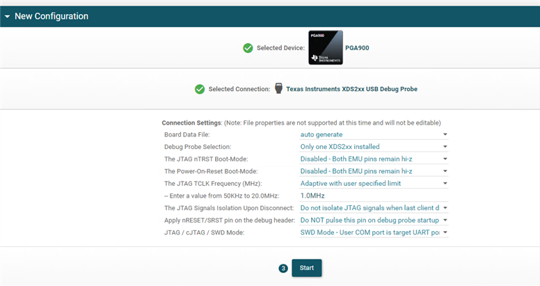
Other Parts Discussed in Thread: UNIFLASH, TIDA-00851

I am using the TIDA00851 board.
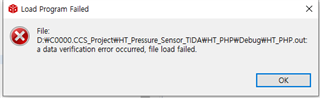
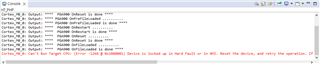
If you compile the provided example code using CCS and debug by connecting the XDS200, the code will operate normally.
If you disconnect XDS, it will operate normally.
If you reapply the power, it will not work.
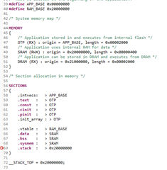
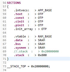
There seems to be a problem with the part where the code is loaded into OTP or DEV RAM, so I called Config_Remap() in the gel file.
{
    WR_MEM_08(REMAP_ADDR,0x00);

}
Even if you change the part to 0x00 or 0x01, the phenomenon of not operating when the power is reapplied is the same.
Is there anything else I can do?

0574.pga900.gel

  • Hello Eunho,

    Welcome to the TI E2E community!

    The engineer that supports this part is currently out of the office and will respond next Tuesday, Nov 14th, when he returns.

    Regards,
    Keith Nicholas
    Precision ADC Applications

  • Hi Eunho Nam,

    Welcome to the E2E forum! I am  currently out of office until Tuesaday. I will reply then. 

    Best regards,

    Bob B

  • Hi Bob!

    Thank you for your support.
    Before you reply, I would like to let you know that I did one more thing.
    When reading memory with uniflash, the following code is contained at address 0x0.

    What's strange is that 0x20000000 also contains a code.
    Please check if this is one of the reasons it is not working now.

    And every time I reapply the power and read the memory with uniflash, the values in the memory (both 0x0 and 0x20000000) keep changing.

    Best regards,

    EHNAM

  • Hello Ehnam,

    Thanks for the additional information.  Bob should be able to provide a response in the next few days.

    Regards,
    Keith

  • Hi Ehnam,

    We need to back up a bit more.  Are you starting with the example firmware project for the PGA900?  If so, what version of CCS are you using?  You should only need to change the gel file settings when using Uniflash for OTP programming.  The following E2E thread may be helpful:

    https://e2e.ti.com/support/sensors-group/sensors/f/sensors-forum/878462/pga900-programming-pga900/3254273#3254273

    Do you have the PGA900EVM?  If so, have you tried the same process with the EVM?  Have you seen and followed the following information as shown in this thread:

    https://e2e.ti.com/support/sensors-group/sensors/f/sensors-forum/807559/ccs-pga900-how-to-run-a-program-in-pg900evm-without-debugging

    DEVRAM is volatile and is useful for development and can overlay the same memory space as OTP.  To actually program the PGA900 OTP (one-time programmable), you need to apply the appropriate programming voltage of 7.5V nominal on the VP_OTP pin.  When using Uniflash and programming the OTP you will need to follow the information regarding the GEL file as given in the first thread I mentioned above.

    Best regards,

    Bob B

  • Hi Bob!

    Thank you for your support.

    I am using the TIDCBJ9 — TIDA-00851 Firmware example project provided by TI.

    To check that the firmware operates properly, unnecessary parts were removed from the example code and the code was structured as follows.

    void main(void)
    {

      M0_ConfigClock(CLK_4MHZ);
      DAC_Reset_Init();
      DAC_Config(DAC_ENABLE, DAC_RATIOMETRIC_MODE_DISABLE, B_4_20MA_EN | DACCAP_EN);
      AMUX_CONFIG(TSEM_N | TEST_MUX_P_EN | TEST_MUX_T_EN | TEST_MUX_DAC_EN);

      DAC_REG0 = 0x2300;

      while(1)
      {
        DAC_REG0 = 0x2300;
      }

    }

    The version of CCS is 12.1.0.00007.

    I do not own PGA900EVM.

    Supply 7.5V through VP_OTP (TP1) and GND (TP2),
    Check the first E2E thread
    Config_Remap()
    {
    WR_MEM_08(REMAP_ADDR,0x01);
    }
    The original above was modified as follows.
    Config_Remap()
    {
    WR_MEM_08(REMAP_ADDR,0x00);
    }

    Then, when you run debug of CCS, the following error appears.

    The following appears in the console window:

    Config_Remap()
    {
    WR_MEM_08(REMAP_ADDR,0x01);
    }
    If I change 0x00 to 0x01 in the gel file above, it debugs normally.
    Of course, if I turn off the XDS200 debugger and re-apply the power, the symptom of it not working remains the same.

    And I have another kind of question.
    Can't I program the OTP memory (address: 0x00000000) multiple times?
    If I first programmed the completed code into OTP, but something changes later, is it possible to modify the code and program it into OTP again?

    Best regards,

    EHNAM

  • Hi Ehnam,

    There are a number of things that need to be addressed.  Let's start with DEVRAM and OTP.  The OTP is not EEPROM and can only be programmed one time, and thus the distinction of one-time programmable or OTP.  This information is in the PGA900 datasheet in section 6.24 where in the table section for OTP it shows the Number of erase/write cycles with a MAX of 1.  This means that once the device OTP is programmed it cannot be changed or updated.  To program the OTP, an elevated voltage is required on the VP_OTP pin where the nominal voltage is set to 7.5V.  The DEVRAM can mimic the memory location of the OTP for checking out and debugging the code prior to writing the code to OTP.  So you verify the operation of your code in DEVRAM first, then once verified it can be written to OTP.

    The DEVRAM is volatile, so you can't turn off the supply and expect the device to restart the way it would when using OTP.  However it does help you debug the operation of the PGA900.  If you are willing to forego using the DEVRAM, you can experiment using the OTP, but this will be a one shot endeavor and you will need to accept throwing away devices as you experiment.

    As to the code, you will need to make a change to the build procedure in CCS.  The library included with the source code is from an earlier compiler so it should not be used.  Instead, under the project properties make the following changes to match what is shown below:

    And remove any additional library include paths except the libc.a library.

    When using Uniflash, make sure the properties match for the device configuration as follows:

    Best regards,

    Bob B

  • Hi Bob!

    I am very grateful for your continued support.

    I understood about OTP and DEVRAM.
    I want to run the code I wrote in the above thread even if I abandon the device.
    This is so that I can understand the process of programming the OTP.
    I plan to understand the programming process for OTP, then write and debug the code I want.

    And once I'm done writing the code, I'm going to program it into OTP.

    so,
    The various options in my CCS General are as follows:

    I edited it like the picture you sent.

    The parts I changed are marked with a red square.

    Change PGA900 to custom arm device in variant and core.

    The arm linker's file search path is the same as the image you sent.

    When I build after completing the settings, the following error occurs.

    An error occurs in the PGA900.cmd file.

    When I modify PGA900.cmd as follows and build, the following warning appears.

    If you change the red box in the arm linker's basic option from blank to 0x800 and build, the warning will disappear.

    Then, when debugging, the following error appears:

    Cortex_M0_0: Can't Run Target CPU: (Error -1268 @ 0x1080001) Device is locked up in Hard Fault or in NMI. Reset the device, and retry the operation. If error persists, confirm configuration, power-cycle the board, and/or try more reliable JTAG settings (e.g. lower TCLK). (Emulation package 9.9.0.00040)

    The Connection Settings of uniflash are the same as the settings you sent.

  • Hi Ehnam,

    The code as it was delivered should compile correctly without changes to the .cmd file or changes to the stack settings.  It is possible that the library file did not get built automatically.  As your out file is different than the original code, I suspect that you changed something in the code itself that may be causing the issue for the ISR fault.

    At this point I would highly recommend creating a separate workspace and importing the original project with the changes as shown earlier.  I would also recommend using the Clean option under the Project drop-down to remove the old compilation files.  Also verify that the library file is actually getting built when compiling.  You should get a console warning the first time that the library is getting built and it will take some time to complete the library build process.  After the project compile and link process has completed, try operating the code while using the debugger.  At this point you should be able to run the code using the debugger in CCS.

    Another check to verify that the correct library is available is to find this file in the folder location:

    C:\ti\ccs1240\ccs\tools\compiler\ti-cgt-arm_20.2.7.LTS\lib\rtsv6M0_T_le_eabi.lib

    Once you have verified that you have a working code, you can proceed to the next step of OTP programming.  Here you can use Uniflash with the proper .gel file settings.  Also remember that you must apply the proper programming voltage to the VDD_OTP pin to actually program the OTP memory.

    Best regards,

    Bob B

  • hi Bob B

    Thank you for your support.

    Then, I will summarize what I understood, so please check if it is correct.
    1. Use CCS to connect a debugger to a device to debug code.
    2. Once the code is completed, create a hex file.
    3.gel file WR_MEM_08(REMAP_ADDR,0x00); Modify as follows.
    4. Supply 7.5V to the VT_OTP pin and load the hex file with UNIFLASH.

    How to check if the product is not programmed in OTP memory
    1. Connect the device and XDS and turn on the power.
    2. Click Read Target Device in the memory tab of UNIFLASH.
    3. Check whether the values of addresses 0x0000000 to 0x00002000 are all 0.

    Please let me know if I'm doing something wrong.

    Best regards,

    EHNAM

  • Hi Ehnam,

    The first steps are correct.  As to the checking once programmed in Uniflash I'm not clear enough on how the device will respond.  In the programming step itself you should be able to verify the contents programmed, but once programmed this may not be easily accomplished if the device is reset.  Once the device is programmed and power reapplied (reset condition), the micro will be in a running state and the digital interface disconnected. You will have to experiment to see if what you are proposing actually works.

    Best regards,

    Bob B