This thread has been locked.

If you have a related question, please click the "Ask a related question" button in the top right corner. The newly created question will be automatically linked to this question.

OPT3101EVM: OPT3101EVM

Part Number: OPT3101EVM
Other Parts Discussed in Thread: OPT3101, BW-3P-TF02-PRO, UNIFLASH

Hello,

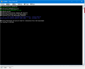
 One customer used OPT3101EVM to extend dynamic range according to the description of datasheet, how to configure the tool and set the parametes except open Super HDR:

Best regards

kailyn

  • Hi Kailyn,

    Our OPT3101 device expert will get back with you on Monday.

    Jalen

  • Kailyn,

    Take a look at https://www.ti.com/lit/pdf/sbaa303 -  Extending the Range of OPT3101 Systems. This app note will provide more information on longer range measurements.

    Using the standard EVM to increase the range will not provide the maximum range the customer may be looking for. The beam angle and sensitivity of the IR LED's play a large factor in range. Some customers use LiDAR to get longer distances. To see how this functions look at:

    EVALUATION BOARD
    BW-3P-TF02-PRO — Benewake TF02 Pro LiDAR module (long-range distance sensor)
    The TF02 PRO module is based on the OPT3101 and is a single-point long-range LiDAR sensor. The sensor is low cost, small size and low power consumption with excellent performance produced by Benewake.
    From: Benewake

    Let me know if you have any further questions. 

  • Gordon

    Use the Super-HDR mode to extend the dynamic range, but at a distance beyond 230mm, the value of the distance does not match the actual length. How to set the drive current of the Super-HDR mode

  • Kailyn,

      You need to do the calibration with the HDR mode turned off. In order to go back to operating mode with longer range you need to turn HDR back on.

  • Gordon:

    Do you calibrate with this configuration?

    Two more questions,

    1, the use of different colors of reflector calibration, the use of dark reflector calibration can normally measure the distance of more than 80mm, the use of white reflector calibration can measure the distance of less than 230mm, what is the reason.

    2. OPT3101 EVM and Latte are used to fix the hardware at a position 150mm away from the reflector. The measurement distance of the black reflector is about 150mm, and the measurement distance of the white reflector is about 180mm,why

  • Pengsheng,

      The calibration requires that the current be set for a specific distance. 

    The white background is the only material used for the distance calibration.

    Make sure the current and distance are set manually and using only the white reflective background. 

    When the calibration is complete, test the distance measurements again with different backgrounds and let me know if the measurements are incorrect. 

  • Gordon:

    Use the OPT3101 Configurator Tool to re-create OPT3101_configuration.cpp in the SDK. The configuration is as follows:

    After 10mm, 20mm, 80mm, 120mm calibration with white background in Step1 simple bringup, the output data is as follows:

    Data larger than 230mm is incorrect. Why

  • Pengsheng,

      Is the distance measured correct below 230mm and or above 230mm after calibration?

  • Gordon:

    After calibration with a white background, configured for Super-HDR mode, the test is correct for distances less than 230mm and incorrect for distances greater than 230mm;

  • Hi Pengsheng,

    Gordon will follow up with you on Monday.

    Jalen

  • Jalen:

    When to reply ?

  • Pengsheng,

     Take a look at the OPT3101Coefficients.cpp file of the SDK. To be honest the automated method using an MSP430 board and the SDK code is the best method of doing the calibration. Read the code, it will walk you through the entire process. It's possible you are missing something in calibration that the automated version in the SDK will resolve. 

    The problems you are seeing are not common with other customers. I recommend that you read through the process in the cpp file. Attempt to recalibrate based on using this method then if it does not work, let me know and please include a very detailed description of your test setup and procedure. I will review it and get back to you. 

  • Pengsheng,

    Sorry for the delay due to the holiday break. I will notify of this thread.

    Jalen

  • Gordon:

    This is my calibration procedure:

    1,Set the working mode to Super-HDR,Create OPT3101_configuration.cpp file

    2,Replace file in SDK OPT3101_configuration.cpp

    3,Open conditional compilation INLAB STEP 1

    4,Use UniFlash to update firmware

    5,Calibrate according to OPT3101 SDK Users Guide 

    Use black electrical tape to cover the photodiode

    6,Calibrate internal crosstalk

    7,corrects for crosstalk and phase offset

    phase offset calibration in this step requires the target to be set an a specified distance:10mm,20mm,80mm,120mm;

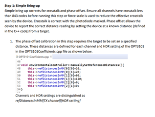
     Use a white background as a reflective surface

    8,Phase offset calibration complete,The read distance is abnormal

  • Pengsheng,

      in the picture you have for image 5, The tape you have on the receiver looks to be a cloth tape. I believe that I can almost see the photodiode through the tape. 

    You need something closer to 100% black out tape or black electrical tape with multiple layers. It has to block out all light including IR light. 

    Please update the black out on the receiver and recalibrate it again. 

    This may be your issue. 

    Let me know your results.

  • Gordon:

    This time, black electrical tape was used to cover the photodiode

    Calibrate internal crosstalk


    ,corrects for crosstalk and phase offset

    If the data is larger than 230mm, the reading data is still incorrect

  • Pengsheng,

      This is not a problem we have seen in the past. Have you tried a different OPT3101EVM? I was just wondering if a second board acts the same way.

    I am attempting to replacate your problem with a setup here that is similar to your setup and settings. I will get back to you as soon as possible.

  • Gordon:

    It is normal to use Latte software to test EVM hardware ranging function;

    The calibration function was tested using another EVM hardware, and the test results were not different

  • Pengsheng,

      I am sorry about the delay, it took soime time to find and understand what you were seeing and replacate your problem, them find a solution. This is what we believe is your problem and solution.

    In HDR mode, the current can switch between 2 current settings on one TX channel, and with super-HDR, TX1 can be used to add 2 more current settings.

    What we think is going on here is that the phase offset measurements are not being done at the proper amplitude for each current setting.

    The documentation recommends doing phase offset calibration at a target distance where the amplitude is between 16000-24000. The preset values in the SDK are arbitrary and definitely don’t follow this rule. The values are set like below in OPT3101Coefficients.cpp.

    void environmentalController::manuallySetReferenceDistances(){

           this->refDistancesInMM[0][0]=50;

           this->refDistancesInMM[0][1]=120;

           this->refDistancesInMM[1][0]=60;

           this->refDistancesInMM[1][1]=150;

           this->refDistancesInMM[2][0]=0;

           this->refDistancesInMM[2][1]=0;

    The indexing on refDistancesInMM is [Tx channel] and [current setting, 0 being H and 1 being L]. In order for them to find the proper distances to set for each current and tx setting, you will need to change your configuration to do just one current, flash that, and see at what distance you can get 16000-24000 codes for that particular current. At higher currents, that distance will be pretty far with a white background, so you can use darker backgrounds in order to get lower amplitude settings, but they’ll need to remember what current settings used what color background when you do the calibration.

     Once you know these distances, you can enter that into OPT3101Coefficients.cpp and then use super-HDR configuration and perform the calibration.

    This method is used to get extended range because it moves the IQ data calculations into the other quadrants. For more information look up IQ demodulation techniques. 

    It's important to tknow that this part is not Direct TOF but Indirect TOF and calculates distance based on the phase angle not a single pulse time. This is why this part is so much better and accurate.

    Let me know how this works. 

  • Gordon:

    What materials are recommended for calibrated reflectors? Whether Lambertian surfaces need to be calibrated using LiDAR,

  • Pengsheng,

      I use a heavey weight card stock 90+ bright white, 300mmx300 and a flat black low pile carpet, 300mmx300mm. I set the height of the OPT3101EVM to emimit and receive in the middle of the reflectors. The distance is determined by the amplitude of the reflective signal.

    No it is not required to use Lambertian surfaces. It is somewhat expected that the reflective angle will be 180 degrees. 

  • Gordon:

    I have tested and completed the calibration function of INLAB_STEP_1 and carried out the next calibration. I have a question to ask:

    1:Whether the phase offset parameters after INLAB_STEP_1 calibration are stored in the MSP430F5529LP during INLAB_STEP_2 step calibration;

    2:To estimate the environmental phase offset coefficient, bright environmental light sources such as halogen lamps are needed, and can be replaced with LED light sources

    3:For phase offset temperature test and lighting crosstalk temperature test in the hot chamber, there are no requirements on air humidity

  • Pengsheng,

      In the OPT3101Coefficients.cpp file in the SDK is the location that you will insert the results from each step of the calibration sequence. No the data is not saved automatically. You will need to capture it in the UART window where the feedback is presented, then inserted into the the calibration file. This will need to be done for each step of the calibration.

    The purpose of the Light is to represent strong ambient light or sunshine. You need about 100k LUX of light. The EVM has a photodiode with IR pass filter and an LED has a narrower bandwidth than sunlight. You should use halogen because an LED won’t have any IR.We recommend halogen lamp due to matching close to sunlight.

    The only time humidity will impact light measurments is 90+ percent humidity (97-100 is fog, rain or under water) We recomment less that 80 percent humidity for the calibration.

    Hopefully you are making good progress on the calibration. Based on your questions and other customers as well, I am rewriting the calibration document. It will be after the new year, but your questions and comments are helpful. 

  • Gordon:

    What I mean is that when I execute INLAB_STEP_1 in OPT3101 SDK, the calibrated phase offset parameters are saved in MCU FLASH. When I perform INLAB_STEP_2 step calibration, will the previous parameters in FLASH be erased;

    I have another question:

    Test the OPT3101 SDK INLAB STEP 4

    Serial port output:Set Ambient light to 0lux 

    How to set 0 Lux? 

    Thanks!

  • Pengsheng,

      I will have to get back to you on Monday. I hope that is alright. I'm not in a place to be able to answer these today. 

  • Pengsheng,

    For step 4 ambient cal Look at 3.6.3 Phase offset Ambient coefficient in the how to calibrate doc. It does not mean to mask the photodiode. You need to sweep ambient light from 0 to max (see Figure 7. Phase offset vs Ambient data)

    The SDK only erases when the writeToFlash/EEPROM command is called. I believe SDK is by default storing in local file on the PC assuming they are running SDK on windows PC. And then load calibration functions called it writes the file values into 3101. There is a flash in the calibration functions if you want to saveToFile or use EEPROM.

  • 戈登:

    OPT3101 EVM 中添加了 24C02 EEPROM。测试步骤INPRODCTION,工厂调整,工厂模式安排完成,调整参数保存EEPROM中;但工厂调整只在调整了相移,例如灯光串干扰温度系数、相偏温度系数、相位环境系数需要软件加载到SDK中,尚未写入EEPROM。请问如何将这些参数写入外部EEPROM?OPT3101通过什么方式可以在上电时自动从EEPROM中加载这些保存的参数;

    我使用外部化EEPROM测试了工厂模式调整,dev.resetInitAndViewData(99999, true);函数中的参数必须为true,否则串口打印的距离数据不正常。

    查看OPT3101数据手册,支持上电自动加载EEPROM中存储的调整参数,我的理解是在外部EEPROM的情况下不需要软件加载这些参数,只需要通过IIC读取相位数据,计算距离;

    谢谢!

  • Pengsheng,

    SDK does not write/load the system level coefficients to EEPROM because these values should not change across devices so won't need to change values in OPT3101Coefficients.cpp when loading firmware to a different unit.

    The EEPROM is read by the OPT3101 on device reset and the device loads the EEPROM values into the registers. More detail in page 32 of the datasheet.

    I will end and lock this thread. Please feel free to start a new question at any time. We like the E2E questions to be individual questions to make it easier for others the track and find solutions. When the question continues but also goes in a different direction it needs to be closed and locked. 

    Thank you.