This thread has been locked.

If you have a related question, please click the "Ask a related question" button in the top right corner. The newly created question will be automatically linked to this question.

PGA970: PGA970EVM

Part Number: PGA970
Other Parts Discussed in Thread: USB2ANY

Hi,

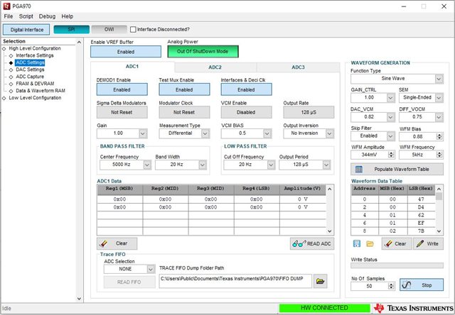
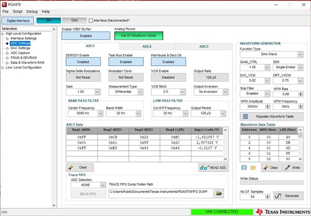
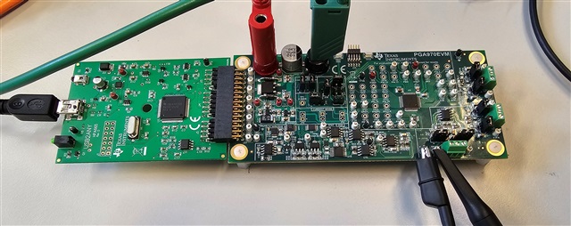
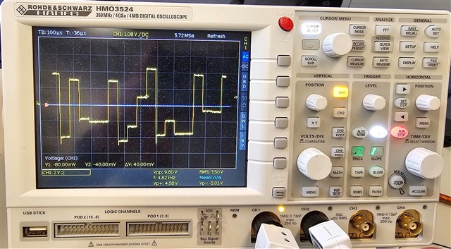
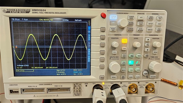
Recently, I bought a "PGA970EVM" and I tested with a 5-wire LVDT, I got a nice Sinus wave on primary coil and also output signal was good as well.

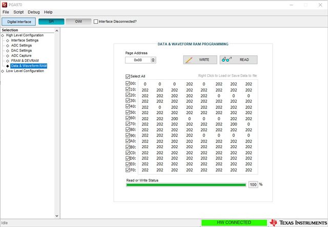
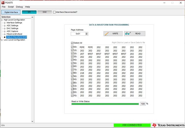
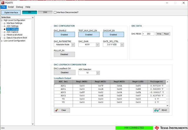
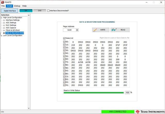
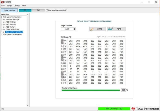
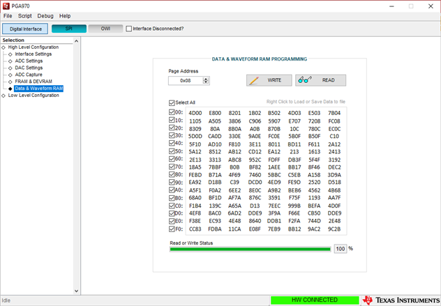
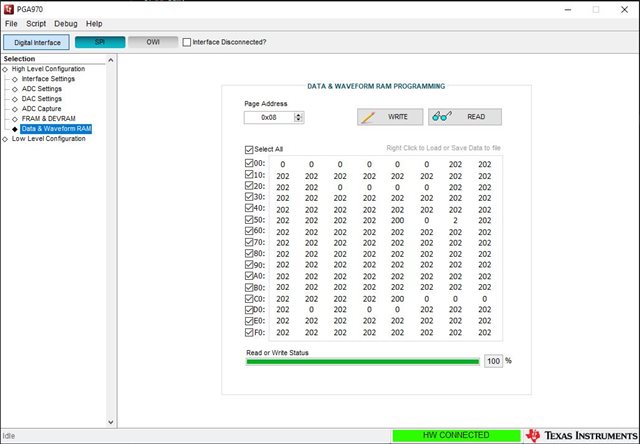
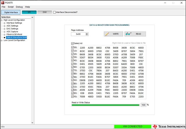
But I don't know what's happened now, I don't have any signal. And when I press the READ button on the "Data & Waveform RAM" it shows just "202" and "0"

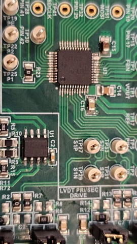
Nothing else. I measured TPs voltage:

External PS: 24V

T2: 4.98v

T3: 7.4v

T4:3.29v

TP6(AVDD): 2.99v

TP9(DVDD): 1.84v

could you please help?

Thanks

Hassan

  • Hi Hassan Samadi,

    The engineer responsible for the PGA970 support is out of the office until tomorrow, therefore please expect a response sometime in the next few days. Thanks for your patience

    -Bryan

  • Hi Hassan,

    Make sure that when you are reading the waveform RAM that you are reading from the correct memory location.  Waveform RAM is on page address 1 and not page address 0.

    If you are still having issues, I would suggest closing the GUI, unplugging the USB cable and repowering the EVM.  Then restart the application as you did originally.  Sometimes the GUI and the PGA970 can get out of sync.

    Best regards,

    Bob B

  • Hi Bob,

    I did all steps that you mentioned, and I reinstalled the PGA970EVM (uninstall and then install again) and ran the software with same settings as I did before. But I get same result, there is no sinus signal on P1A and P2A and RAM is always full of random data.


  • Hi Hassan,

    I must admit I am somewhat confused by the Data and Waveform RAM table.  The first page address of the waveform table (first 256 bytes of the 512 byte table) is actually Page Address 0x08 and the second 256 bytes is Page Address 0x09.  This page scheme does not coincide with the datasheet unfortunately.  Instead of trying to read the RAM could you actually just look at the output on a scope at the P1A test point? 

    I'm confused by the last screen shot where you are apparently able to read ADC1 data but you haven't turned on the waveform generator.  So when you restarted, did you write the waveform table to the device and then did you turn on the generator by selecting the Generate button?

    Just as some additional information, if you happen to place the ADC modulator clock into the Reset state, the waveform generator will stop working.

    Best regards,

    Bob B

  • Hi Bob,

    this screenshot is just about that I stopped the wave generator, but as I said it sometimes gives a random Square wave with too many noises on it and when I read the ADC then it just jumps for example from -3.xxx v to +3.xxx v and some other random values.

    I read all data in FRAM it always gives random values everywhere.

    Of course, after setting the parameters on "Waveform generator", I Press "Populate waveform table" then "write" button", and finally "Generate" button. But it is always zero on P1A and P2A, I have checked with Oscilloscope too.

    Best wishes

    Hassan

  • Hi Hassan,

    Unfortunately I've run out of suggestions.  I don't see the issues you are seeing.  Perhaps the PGA970 was damaged in some way or there is a communication issue with the USB2ANY.

    One thing you could try is to check the communication by reading/writing the Low Level Configuration registers to see if yo get the proper response.

    Best regards,

    Bob B

  • Hi Bob,

    I have another USB2ANY and tested with that, but I got same result.

    When I press the "Read All" button, every time the data in registers changed.

    With connecting Oscilloscope, sometime I get this kind of signal on P1A.

    Another issue is when I connect the Scope between P1A(CH1) and P2A(Scope-Gnd) then U1 get too hot.

    In this case, I connect the CH1 to P1A and Scope-Gnd to TP45(GND) and I get the signal like attached photo.

    I took screenshots of all settings, Hardware and Scope. Could you please check them

    Best wishes

    Hassan

  • Hi Hassan,

    The RAM memory is a bit messy and that is the reason why the waveform is in correct.  Part of this may be due to the register settings blocking or corrupting certain features.  Can you power down and restart the system but don't make any changes.  Just keep the selection on the Low Level Configuration and also select Digital Interface (instead of Microcontroller).  Then select the icon for Read All.  Once the registers are read, select the Save icon, then save the file and attach the file to the thread.

    Then go to the ADC settings page and only change the WFM frequency to 5kHz and leave everything else as default values.  Then Populate Waveform Table and Write the table to memory.  Then go to the Data & Waveform RAM and read Page Address 0x08 and attach a screen shot.  Below is what mine looks like:

    Because the data in your table in the previous post was incorrect, the waveform generated would also be incorrect.  What I'm hoping to see is the simplest configuration possible to determine what is happening.  It is quite possible that your part has been damaged.

    What were you doing prior to the failure condition?  Is there something you haven't told me because you may consider it unimportant?  Did you attempt writing to the FRAM?

    Best regards,

    Bob B

  • Hi Bob,

    I did everything according to the steps that you mentioned, this is the result. I tried once more but same result:

    As I said, at first I got a nice sinus on P1A and also connected a 25mm-LVDT, the signal on ADC and DAC was perfect. I also measured with Scope and multimeter. After that I removed 25mm-sensor and connected a 10mm-sensor, then I have never got those signals again. I also wanted to test the FRAM, then I loaded the hex file of "PGA970_FW_Release_1_6_Generic" through "FRAM & DEVRAM" page, but I didn't work too.

    Best Regards,

    Hassan

  • Hi Hassan,

    In my last post I requested the following:

    Can you power down and restart the system but don't make any changes.  Just keep the selection on the Low Level Configuration and also select Digital Interface (instead of Microcontroller).  Then select the icon for Read All.  Once the registers are read, select the Save icon, then save the file and attach the file to the thread.

    Can you do that for me to see if the registers are powering up to the correct default values.  I fear that by attempting to write hex file something either didn't complete correctly or there is some issue related to writing the FRAM.  The PGA970 is an open core M0 processor with various analog circuitry.  It would appear that the PGA 970 is acting strangely is due to corrupted FRAM data space which in turn is corrupting the RAM space.  

    The PGA970 is a very complex and complicated device and has a very limited support model due to limited staffing resources.

    https://e2e.ti.com/support/sensors-group/sensors/f/sensors-forum/802433/what-is-the-e2e-support-model-for-the-pga900-and-pga970

    When you tried to reload the hex file, did you use the prebuilt file from the project, or did you attempt to use CCS and rebuild the file?

    Best regards,

    Bob B

  • Hi Bob,

    this is the screenshot of memory:

    I disconnected the power of the PGA970EVM and then "Read All" in "Digital interface" mode then "save configuration"

    In "ADC Settings" page, I just changed the freq. to 5KHz and "Populate Waveform Table" and "Write" and finally "Read" the page address: 0x08 in "Data & Waveform RAM" page.

    But I think result get changed from the last time.

    Read All_PowerDown.cfg

    ****When you tried to reload the hex file, did you use the prebuilt file from the project, or did you attempt to use CCS and rebuild the file?****

    I wanted to compile the file in CCS, but I got Error, then I used the hex file in folder.  But in "Data & Waveform RAM" page I changed the words and then pressed the "Write" button.

    Best Regards,

    Hassan

  • Hi Hassan,

    The file you sent does not have the expected startup values.  When you attempted to download the hex file, did you verify that the code downloaded properly?  Although it is possible to download code directly to the PGA970 using the GUI, the best method of using the EVM and code verification is by using the XDS200 debugger tool and CCS.  The example project was written with a much older version of the compiler than what is currently available.  Perhaps the following E2E thread will help you get a better start on the code application:

    https://e2e.ti.com/support/sensors-group/sensors/f/sensors-forum/1268193/pga970-what-does-the-pga970_fw_release_1_6_generic-hex-file-do/4802924#4802924

    So it would appear that the code for the PGA970 has been erased from the device on the EVM.  It is unclear how this actually happened.  It is uncertain if it is still possible to download the hex file using the GUI without the use of a debugger.  In the end you will need to having working code in the device before you can do anything with it.

    Best regards,

    Bob B

  • Hi Bob,

    after I test SPI signal Both side of U7 (MOSI, MISO, CLk, CS) I realized that PGA970 worked but not completely, I measured all voltage and TPs again I got that maybe Half of the PGA970 works, I mean sensor side was broken, I decided to remove the PGA970 and solder a new one on the board. After testing, it works again. I should say that I replaced a U1 with another similar IC, but I think the U1 worked ok that was unnecessary.

    And these are the results:


    Thanks Bob for your help and time. In the next step, I want to continue with CCS and programming.

    Best regards,

    Hassan

  • Hi Hassan,

    I'm glad you were able to make some progress.

    Best regards,

    Bob B