This thread has been locked.

If you have a related question, please click the "Ask a related question" button in the top right corner. The newly created question will be automatically linked to this question.

AWR6843AOP: Radar cube memory status in L3

Part Number: AWR6843AOP
Other Parts Discussed in Thread: AWR6843, AWRL6432, AWRL1432

hello , 

first thanks for quickly reply.

i checked radar cube size by using estimator tool.

also, i want to know total chirp status & radar cube memory in blow parameter.

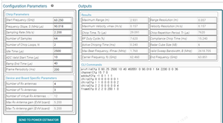
Q1. Is it coorect that the chrip drawing per frame is drawn as shown below?[using AWR6843 aop]

      Q1-a. drawing  of Loop & Frame Periodicity 

are the definitions of loop and periodic time same?

   Q1-b. drawing of chirp


is it right? is it coorect that there are 3 chrips per loop?

Q1.c Radar cube mormoy

accroding to estimator , radar cube size is 6kb ( range bin(64) * virtaul ant(12) * loop(2) = 6kb)

then, do the values in the first array mean the 3chrip FTT values?

i am anayzing the radardemo_aoaEst2DCaponBF_clutterRemoval function, but i am very conufsed because of radar cube memory.

please share your opion.

  • please solve my confusion T.T..

  • Hey Jihnhyun,

    Thanks for reaching back out to us regarding radar transmission and radar cube storage. First of all, its important to note that an entire frame can consist of multiple chirps and many timings which are dependent on the software configuration/CLI commands and the selected device. The information I will share for software configurations will be in relation to SDK 3 devices, but note that SDK 5 devices, such as AWRL1432 and AWRL6432, are configured differently. I'll answer your questions in order:

    1. Yes, this is an accurate representation of the chirps for a given frame.
      1. Loop time and frame periodicity are different. Loop time is roughly calculated as the chirp repetition period in the sensing estimator - i.e., number of Tx/chirps * (idle time + ramp end time) - and frame periodicity is inputted through the frameCfg. You may notice that the chirp repetition period * number of loops does not equal the entire frame time. This means the device idles for the remaining time which is sometimes called interframe idle time.
      2. Yes, there are three chirps per loop for this given configuration that are received at four different Rx antennas. 
      3. For the array shown, each range bin would be a four byte FFT value for one chirp from Tx0 received at Rx1. The dimensions of the radar cube correspond to which chirp was transmitted, which antenna received the chirp, and what range bin was sampled - see below link for more information.

    I would recommend reading through "What Does Radar Data Look Like?" under the Radar Academy to learn more about how chirps are transmitted, what composes a frame, and how the output data will look. Let me know if you have any other questions or need some clarification.

    Regards,

    Kristien