This thread has been locked.

If you have a related question, please click the "Ask a related question" button in the top right corner. The newly created question will be automatically linked to this question.

AWRL1432: Problem with getting data for angle FFT from SDK

Part Number: AWRL1432
Other Parts Discussed in Thread: AWR1642

Hi,

    I am working on the MMW demo in SDK 5.3, using BPM mode. I am trying to get the data for angle FFT from the SDK.

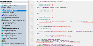
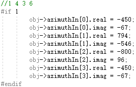
    I first determined the range index based on the distance of the corner reflector in the darkroom, and then output the data corresponding to this range index in the aoa2dProc_CopyMapAntSymbols() function, that is, srcScratchPad [src].real and srcScratchPad[src].imag, as shown below:
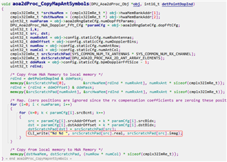
    

    One set of data is as follows: -450 -67, 522 -231, -800 96, 794 -546, -450 -67, -450 -67, 600 34, -684 342.

    There are 8 channels of data. According to my understanding of the code, I think the first 4 channels are azimuth dimension data.

    However, after I did FFT on the data of the first 4 channels, the angle I finally got was wrong.

    I'm considering using other algorithms instead of FFT to get better angle accuracy, so I'm hoping you could help me confirm if the way I'm getting the data is correct, and if not, how should I get the data?

Thaks!

  • Hello.

    Have you tried using the azimuth elevation heatmap TLV to get the angle data instead?  If you parse the UART data stream coming from the device, it is one of the TLVs that is sent from the device.  You can find more information on this TLV and other TLVs that may be helpful in this guide.

    Sincerely,

    Santosh

  • Hi,

      I checked the document and found that there is only static range-azimuth heat map data in TLV, but I need to obtain all target data after cfar. 


      In addition, I checked the code and found that both result->rngAzHeatMap and result->rngAzHeatMap were assigned the same address gMmwMssMCB.detMatrix.data. Is this a bug?


      So, back to my original question, could you please confirm if the way I'm getting the data is correct, and if not, how should I get the data?

    Thanks!

  • Hello.

      In addition, I checked the code and found that both result->rngAzHeatMap and result->rngAzHeatMap were assigned the same address gMmwMssMCB.detMatrix.data. Is this a bug?

    No, that is due to either being set from major motion or minor motion.

    So, back to my original question, could you please confirm if the way I'm getting the data is correct, and if not, how should I get the data?

    That should be correct, but let me confirm that this and get back to you by Monday.  However, using CLI_write may not always be the best option as it takes time to do this and there can be some data loss.  If you do raw data capture to get the ADC data, you may get more accurate results, but will have to do all the appropriate processing to get the doppler information needed to perform the angle FFT.  Please refer to this guide here for more information on raw data capture.

    Sincerely,

    Santosh

  • Hi,

    both result->rngAzHeatMap and result->rngAzHeatMap

      Sorry, I made a mistake here, what I want to say is "both result->rngAzHeatMap and result->rngDopplerHeatMap", I think result->rngAzHeatMap should not be assigned as gMmwMssMCB.detMatrix.data, because gMmwMssMCB.detMatrix.data is the data after non-coherent accumulation of all channels, right?

    However, using CLI_write may not always be the best option as it takes time to do this and there can be some data loss. 

      I used a baud rate of 1250000 so that CLI_write would take less than 1ms. I eventually need to implement other DOA algorithms on the EVM, so I need to verify the correctness of the data first, and after that, I will remove this printing.

      I have verified the correctness of the 3D FFT with other data, so the reason for the wrong angle results should come from the input data, or the way I use the data:

    I think the first 4 channels are azimuth dimension data.

        However, after I did FFT on the data of the first 4 channels, the angle I finally got was wrong.

    Thanks!

  • Hello.

     I think result->rngAzHeatMap should not be assigned as gMmwMssMCB.detMatrix.data, because gMmwMssMCB.detMatrix.data is the data after non-coherent accumulation of all channels, right?

    At this point, the detection matrix data is the range-azimuth heatmap, so the non-coherent combination to create the range-azimuth heatmap has already been performed and assigned into the detection matrix.

      I have verified the correctness of the 3D FFT with other data, so the reason for the wrong angle results should come from the input data, or the way I use the data:

    How off is the accuracy of your angle estimation in comparison to what you expect?  It is possible for the estimation to be off by a couple degrees as you move away from the boresight of the sensor.  In addition, is your FFT computation done the same way as what is done in the hardware accelerator?

    Sincerely,

    Santosh

  • Hi,

    How off is the accuracy of your angle estimation in comparison to what you expect?

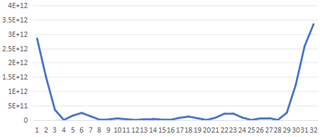
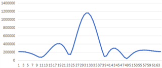
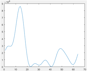
      For the data of the front corner reflector measured by AWR1642, the results I obtained after doing FFT and magnitude squared (without fftshift) are as follows:

      These data are obtained after I processed the ADC data on visual studio.

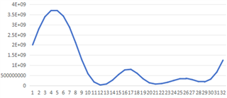
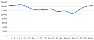
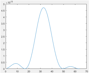
      For AWR1432, the results are as follows (for the corner reflector at the same position):


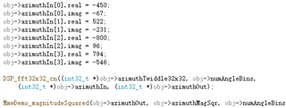
    The same fft function is used: DSP_fft32x32_cn, but obj->azimuthIn is replaced with AWR1432 data (as mentioned at the beginning of this post):
      

    is your FFT computation done the same way as what is done in the hardware accelerator?

      What I am using is DSP_fft32x32_cn, the path is C:\ti\dsplib_c64Px_3_4_0_0\packages\ti\dsplib\src\DSP_fft32x32\c64P. 

      This was just tested on visual studio, and since the AWR1432 doesn't have a DSP, I wouldn't actually use this function.

      I'm not sure how big a difference there is. 


      I also tried using DBF instead of FFT to do DOA, using the method mentioned above, but replacing the DSP_fft32x32_cn function with DBF processing.      For AWR1642 data, I can still get the correct results:

      But for AWR1432 data, after DBF processing, the result is still wrong:


    So, I think we probably need to go back here:

    so the reason for the wrong angle results should come from the input data, or the way I use the data

    Thanks!

  • I understand.  I am looking into this and will provide an update by Friday.  Could you provide the angle that you are trying to measure(what angle the corner reflector is placed at with respect to boresight) as well as the center frequency being used in the FFT calculation?

    Sincerely,

    Santosh

  • Hello.

    Instead of checking in that function for the doppler fft output, you could look in the DPU_Aoa2dProc_process and trace where the doppler fft output is computed and stored(temporarily as it is too much to store in memory long term).  You could place a breakpoint at this point and compare the contents in memory to what was printed via CLI_write to make sure that the info is correct.  The function includes comments as to where the doppler FFT is triggered, and the output is stored in the M1 memory bank in the HWA.

    Sincerely,

    Santosh

  • Hi,

      Considering the installation error, the azimuth angle of the corner reflector should be within ±1 degree and the range is about 5.8 meters.
      I'm not sure if my understanding of "the center frequency being used in the FFT calculation" mentioned above is correct, what I can provide is: start frequency: 77G, bandwidth: 174MHz, maximum range: 110 meters.

    Thanks!

  • Hi,

      For the DPU_Aoa2dProc_process function, the position where I can first read the Doppler fft output is in the aoa2dProc_CopyMapAntSymbols subfunction.

    You could place a breakpoint at this point and compare the contents in memory to what was printed via CLI_write to make sure that the info is correct

      I have confirmed that the output of CLI_write is correct.

    Thanks!

  • Hello.

    I have confirmed that the output of CLI_write is correct.

    Thank you for checking this.  Let me look into the format of the doppler information further, and confirm that you are using that correctly.  It looks like you are using the correct data as the input to the FFT, but let me confirm its format as I am still looking into this, and will provide a follow up by Friday.  Just to confirm, you are comparing the output of your angle FFT data with the azimuth data computed from the angle FFT in the processing chain correct?

    Sincerely,

    Santosh

  • Hi,

    you are comparing the output of your angle FFT data with the azimuth data computed from the angle FFT in the processing chain correct?

      Yes, the purpose of the comparison is to verify the correctness of the data I obtained and used.

      I will wait for your reply on Friday.

      Thanks!

  • Hello.

    After looking a little deeper in the function you were writing the data from, I realized that the data is not in any specific order, so you cannot just take the first four channels and take the FFT.  If you copy from the srcScratchpad, you need to grab the values from index 1, 4, 3, and 6, and take the FFT on these channels.  The simplest way is to print the index of srcScratchpad along with your data, and take the data points from the specified indexes above in that order and take the FFT.

    Sincerely,

    Santosh

  • Hi,

      I tried using the 1 4 3 6 sequences, but the result was close to the 1 2 3 4 sequences, and I still couldn't get the correct result.

      This is the data I used:

    One set of data is as follows: -450 -67, 522 -231, -800 96, 794 -546, -450 -67, -450 -67, 600 34, -684 342.


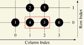
      I'm still a little confused about the data, because the radar has 6 channels, but 8 sets of data were obtained, and I think the redundant 2 sets of data should come from channels 3 and 4, as shown in the picture below:

      But in fact, in the data I got, the 1st, 5th and 6th groups of data are completely equal (I tried several times, and it was always like this):


      Could you please help me confirm that for my existing 8 sets of data, which 4 sets of data should I take in what order to get the data of channels 1, 4, 3, and 2?

    Thanks!

  • Hello.

    The order that the data is printed is not in the order of 1 , 2, 3, 4, 5, 6, but whatever the value of src is.  You need to identify what index src is for that dataset is, and use the ones where src is equal to 1, 4, 3, 6.  From what you have provided, I cannot tell what index value of src is associated with each dataset; you will need to print that out as well to determine this.

    Sincerely,

    Santosh

  • Hi,

      The reason I ask this is that I don't know explicitly the relationship between the printed index and the channel index.

      So, I decided to ask a related question. Below is the link to the question:

      AWRL1432: Questions about the azimuth dimension data in the aoa2dProc_CopyMapAntSymbol function - Sensors forum - Sensors - TI E2E support forums

    Thank you!

  • Hi,

      I need to stay with this original thread, the additional information I can provide is: The value of "numParam" is 4, and each value of "paramCfg[i].srcBcnt" is 2, so I got 8 sets of data.


      For the corner reflector directly in front of the radar, the data obtained from one of the tests is as follows: -450 -67, 522 -231, -800 96, 794 -546, -450 -67, -450 -67, 600 34, -684 342.

      The 1st, 5th and 6th data here are completely equal:


      So, I believe there are 6 independent sets of data, corresponding to 6 channels. For now, I only care about the azimuth dimension. According to the arrangement of the antenna, the channel corresponding to the azimuth angle It's 1, 4, 3, 6.

      I tried reading the MmwDemo_cfgDopplerParamMapping function, but still didn't figure out the relationship between these groups of data and the antenna channels.

      Could you please help me determine which data correspond to channels 1, 4, 3 and 6?

    Thank you!

  • Hello,

    Santosh is out due to the holidays, there will be a delay in response time

    Best Regards,

    Pedrhom

  • Hello.

    As I stated before, the order in which the data is printed out cannot be used in any way to determine which channel it is associated with.  You need to also note the value of src, which is used as an index in the line you boxed in the image.  The value of src will tell you which channel that data is associated with, and that number will indicate the 1st, 3rd, 4th, and 6th channels.

    Sincerely,

    Santosh

  • Hi,

      Sorry, I didn't understand exactly what you meant before. Thank you for your patience.

      I printed the value of src:


      The results are as follows:


      Since the starting index in the code is 0, the first four values "0 3 2 5" actually correspond to "1 4 3 6".

      This is the order I used when asking the question at the beginning of this post:

    There are 8 channels of data. According to my understanding of the code, I think the first 4 channels are azimuth dimension data.

        However, after I did FFT on the data of the first 4 channels, the angle I finally got was wrong.

      So, I still need your help, I can't figure out where the problem is.

      If the data itself and channel sorting are correct, is it possible that the SDK does other processing before triggering HWA to do DOA?

    Thanks!

  • Hello.

    It is possible, but looking at the code, you should be able to get the information you need at that point in the processing chain.  If you can do thing to make sure you are doing the fft on the right data, can you print the index along with data to make sure that it is the same every time, or if the order changes with each run?

    Sincerely,

    Santosh

  • Hi,  

      I used MATLAB to do an FFT on the data, so it looks clearer:

      The result is shown below:

      For the data of 1642 measuring the front corner reflector, using the same FFT calculation, the result is correct:

      So, I think the data processing should be correct.

    can you print the index along with data to make sure that it is the same every time, or if the order changes with each run?

      I verified that for any point cloud in any frame, the order is the same:

      Is it possible to discuss this issue with the development team? I think it may be that HWA processes data differently than I thought.

    Thanks!

  • Hello.

      So, I think the data processing should be correct.

    When you are doing the angle FFT, are you doing any phase/gain calibration?  Please refer to this E2E for information on the phase/gain calibration.  This calibration is usually done in the OOB demo, but if you are just getting the doppler information and doing the angle FFT yourself, you will need to do this calibration as well.

    Sincerely,

    Santosh

  • Hi,

    When you are doing the angle FFT, are you doing any phase/gain calibration?

    I didn't do this for two reasons:

    1. The error in angle measurement is too big. When the number of FFT points was 64, the angle peak index should be around 32, and now it is 14.

    2. In the OOB demo, I did not perform calibration either, but the angle measurement results were correct, these are the parameters I passed in:

    I output the data in the aoa2dProc_CopyMapAntSymbols function, and the next step is to trigger HWA to perform angle calculation, so I am wondering if we can get more details of HWA angle calculation to determine the possible cause?

    Thanks!

  • Hello.

    The implementation details for angle processing can be found in the MmwaveDemo_documentation.pdf in the <sdk-install-location>/docs/ folder.  It can be found in the AoA2D DPU section of the document.

    Sincerely,

    Santosh

  • Hi,

      I looked through the documentation and unfortunately found no information that would help resolve this issue.

      Is there anything else we can try?

    Thanks!

  • Hello.

    One thing you could try is taking the raw ADC data and then going through all the processing you have written offline, and then use this to confirm whether you are implementing the algorithm for AoA processing correctly or if the data you are using is incorrect.  Have you done this yet as a way of verifying your algorithm?

    Sincerely,

    Santosh

  • Hi,

      Since there is a problem with the DCA1000 board, I haven't done this yet, I will find a way to solve this problem.

      Thank you very much for your help!

  • No problem!

    If you have any questions on the DCA1000 EVM, feel free to look up your issue on E2E or post a new question on the E2E forum!

    Sincerely,

    Santosh