This thread has been locked.

If you have a related question, please click the "Ask a related question" button in the top right corner. The newly created question will be automatically linked to this question.

AWR6843AOP: IWR6843AOP&DCA1000 collect CW mode data

Part Number: IWR6843AOP

Hello,TI's engineer:

I meet some trouble when i use IWR6843aop and dca1000 to collect data under CW mode.

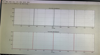
I set digOutSampleRate 2000kps,complex,I first.Then i read the data with matlab,i find the I or Q data 1028 point is a cycle,the first four numbers are all 2047.

It makes me wonder if I've configured it wrong.I would like to know what is the data format of 6843 and DCA1000 in CW mode configured by mmWave studio.

Thanks for your reply.

BR

Bryant

  • Hello,

    The Mmwave Radar Device ADC Raw Data Capture App note should have file format for 6843+DCA1000 explained. 

    Thanks,

    E. Shareef

  • HI,

    We read the doc and refered the format,LFMCW wave config is ok,however CW mode is still have 8 point unusual.You can try it.

    BR

    Bryant

  • Hi,

    There is dataTransSize setting in ADCBuf_control call in mmwave SDK, but we can't find such setting in mmWave studio.

    typedef struct MMWave_ContModeCfg_t
    {
    /**
    * @brief Continuous mode configuration
    */
    rlContModeCfg_t cfg;

    /**
    * @brief Sample count: This refers to the number of samples per
    * channel.
    */
    uint16_t dataTransSize;
    }MMWave_ContModeCfg;

    Is the dataTransSize of Contimode fixed in mmWave studio? Is the unexpected data in captured ADC data is related to this?

    Thanks,

    Chris

  • HI, Chris:

    Please give us some time to get back to you.

    Best,

    Zigang

  • Hello,

    Could you give more details into your setup? When using CW mode, you have a zero slope chirp. If you transmit a zero slope chirp and reflect it (or loop it back) to the device, the mixers will mix it back to DC. Special care must be taken to ensure that the signal sent into the RX chains is shifted above the above the HPF cutoff so that you will see a signal. Is this being done?

    Best Regards,

    Pedrhom

  • Hello Chris,

    A properly configured continuous wave mode signal has to have 0 slope, and is contradictory otherwise. Continuous wave mode has a constant amplitude and frequency, and a slope would increase the frequency and make it FMCW. In the mmWaveStudio installation where there are scripts, there is DataCapture_CascadeCW.lua which is similar to the one referenced in that thread. In DataCapture_CascadeCW.lua there is a line that sets slope to 0.

    Best Regards,

    Pedrhom

  • Pedrhom,

    For contistream, there is not setting for slop. Yes. the slop of a CW stream is 0.

    Would you pls try the method in the post I shared and reproduce the problem? 

    Thanks,

    Chris

  • Hello Chris,

    The behavior they are seeing is not normal. Please provide a detailed description of their continuous wave experimental set up. I would like to know what signal is being injected into the RX chain in CW mode. For instance, are they using the TX signal from the device in CW mode and looping it back to RX via target reflection, corner reflector, or coax cables? A complete CW configuration information along with details of the physical set-up will help me immensely.

    Best Regards,

    Pedrhom

  • Pedrhom,

    I tried to reproduce the problem at my end. Pls find detail in below. Any question, pls let me know.

    IWR6843AOP_CW.docx

    Thanks,

    Chris

  • Hello Chirs,

    First off, the settings start frequency of 77GHz on an industrial 60GHz device is going to cause issues and is a problem. But ultimately, you cannot use this style setup if using CW mode because you need a type of known tone sent to the device, and the tone must be shifted certain amount of MHz in order to create a difference so that the intermediate frequency is not 0.

    So I want to ask specifically why is CW mode being used and are they adamant on using. We genuinely never encourage the use of it due to the lack of information it provides for common use cases in the FMCW MIMO radar space. We only use CW mode if there is a specific antenna test they are trying to do, or specific performance metrics or calibrations they are trying to meet. If they are doing standard testing, then we strongly encourage they move to a real chirp configuration that creates a non-zero IF and thus not using CW mode.

    Best Regards,

    Pedrhom

  • the settings start frequency of 77GHz on an industrial 60GHz device is going to cause issues and is a problem

    This is a mistake. After you run the LUA, the start frequency of Contistream tab will change to 60G automatically. I corrected the info. Pls find update doc below.

    IWR6843AOP_CW_0206.docx

    I also saved the mmWave studio output log for your reference.

    [13:49:04]  [RadarAPI]: ar1.PowerOff()
    [13:49:04]  [RadarAPI]: Status: Passed
    [13:49:05]  [RadarAPI]: Opening Gpio Control Port()
    [13:49:05]  [RadarAPI]: Status: Passed
    [13:49:05]  [RadarAPI]: ar1.Disconnect()
    [13:49:05]  [RadarAPI]: ar1.Calling_ATE_DisconnectTarget()
    [13:49:05]  [RadarAPI]: ar1.Calling_IsConnected()
    [13:49:05]  [RadarAPI]: ar1.SaveSettings('C:\Users\a0389162\AppData\Roaming\RSTD\ar1gui.ini')
    [13:49:05]  [RadarAPI]: Opening Board Control Port()
    [13:49:05]  [RadarAPI]: Status: Passed
    [13:49:06]  [RadarAPI]: ar1.FullReset()
    [13:49:06]  [RadarAPI]: Status: Passed
    [13:49:07]  [RadarAPI]: Closing Board Control Port()
    [13:49:07]  [RadarAPI]: Status: Passed
    [13:49:07]  [RadarAPI]: Closing Gpio Control Port()
    [13:49:07]  [RadarAPI]: Status: Passed
    [13:49:07]  [RadarAPI]: ar1.SOPControl(2)
    [13:49:07]  [RadarAPI]: Status: Passed
    [13:49:09]  [RadarAPI]: ar1.Connect(8,921600,1000)
    [13:49:11]  [RadarAPI]: Warning: Connected with baudrate 115200
    [13:49:12]  [RadarAPI]: Warning: Disconnected existing BaudRate
    [13:49:13]  [RadarAPI]: Warning: Trying to connect with baudrate 921600
    [13:49:14]  [RadarAPI]: ar1.Calling_IsConnected()
    [13:49:15]  Device Status : UnDetDe/ASIL-B/SOP:2/ES:2
    [13:49:15]  [RadarAPI]: ar1.SaveSettings('C:\Users\a0389162\AppData\Roaming\RSTD\ar1gui.ini')
    [13:49:17]  [RadarAPI]: ar1.ReadRegister(0xffffe214, 0, 31)
    [13:49:17]  [RadarAPI]: ar1.ReadRegister(0xffffe210, 0, 31)
    [13:49:17]  [RadarAPI]: ar1.frequencyBandSelection("60G")
    [13:49:17]  [RadarAPI]: ar1.SelectChipVersion("IWR6843")
    [13:49:17]  [RadarAPI]: Status: Passed
    [13:49:17]  [RadarAPI]: ar1.ReadRegister(0xffffe218, 0, 31)
    [13:49:17]  [RadarAPI]: ar1.DownloadBSSFw("C:\\ti\\mmwave_studio_02_01_01_00\\mmWaveStudio\\Scripts\\..\\..\\rf_eval_firmware\\radarss\\xwr68xx_radarss.bin")
    [13:49:18]  [RadarAPI]: Downloading BSS ROM RPRC Binary..
    [13:49:25]  [RadarAPI]: ar1.GetBSSFwVersion()
    [13:49:25]  [RadarAPI]: BSSFwVersion:(06.02.01.05 (09/03/20))
    [13:49:26]  BSS FW Download Success
    [13:49:26]  [RadarAPI]: ar1.DownloadMSSFw("C:\\ti\\mmwave_studio_02_01_01_00\\mmWaveStudio\\Scripts\\..\\..\\rf_eval_firmware\\masterss\\xwr68xx_masterss.bin")
    [13:49:26]  [RadarAPI]: Downloading MSS RPRC Binary..
    [13:49:29]  [RadarAPI]: ar1.GetMSSFwVersion()
    [13:49:29]  [RadarAPI]: MSSFwVersion:(02.00.00.03 (27/08/19))
    [13:49:29]  MSS FW Download Success
    [13:49:30]  MSS power up done async event received!
    [13:49:30]  [RadarAPI]: ar1.PowerOn(0, 1000, 0, 0)
    [13:49:30]  [RadarAPI]: Status: Passed
    [13:49:30]  Power On Success
    [13:49:31]  Device Status : UnDetDe/ASIL-B/SOP:2/ES:2
    [13:49:31]  [RadarAPI]: ar1.RfEnable()
    [13:49:31]  BSS power up done async event received!
    [13:49:31]  [RadarAPI]: Status: Passed
    [13:49:32]  [RadarAPI]: ar1.GetMSSFwVersion()
    [13:49:32]  [RadarAPI]: MSSFwVersion:(02.00.00.03 (27/08/19))
    [13:49:32]  [RadarAPI]: ar1.GetBSSFwVersion()
    [13:49:32]  [RadarAPI]: BSSFwVersion:(06.02.01.05 (09/03/20))
    [13:49:32]  RF Enable Success
    [13:49:32]  [RadarAPI]: ar1.ChanNAdcConfig(1, 1, 0, 1, 1, 1, 1, 2, 1, 0)
    [13:49:33]  [RadarAPI]: Status: Passed
    [13:49:33]  ChanNAdcConfig Success
    [13:49:33]  [RadarAPI]: ar1.LPModConfig(0, 0)
    [13:49:33]  [RadarAPI]: Status: Passed
    [13:49:33]  Regualar mode Cfg Success
    [13:49:33]  [RadarAPI]: ar1.RfInit()
    [13:49:33]  RF Init async event received!
    [13:49:33]  [RadarAPI]: Time stamp, Temperture: 1813,36; APLL Status, Update: 1, 0; SynthVCO1 Status, Update: 1, 1; SynthVCO2 Status, Update: 1, 1; LODist Status, Update: 1, 1; RxADCDC Status, Update: 1, 1; HPFcutoff Status, Update: 1, 1; LPFcutoff Status, Update: 1, 1; PeakDetector Status, Update: 1, 1; TxPower Status, Update: 1, 1; RxGain Status, Update: 1, 1; TxPhase Status, Update: 1, 1; RxIQMM Status, Update: 1, 1; 
    [13:49:33]  [RadarAPI]: Status: Passed
    [13:49:33]  RfInit Success
    [13:49:34]  [RadarAPI]: ar1.DataPathConfig(1, 1, 0)
    [13:49:34]  [RadarAPI]: Status: Passed
    [13:49:34]  DataPathConfig Success
    [13:49:34]  [RadarAPI]: ar1.LvdsClkConfig(1, 1)
    [13:49:34]  [RadarAPI]: Status: Passed
    [13:49:34]  LvdsClkConfig Success
    [13:49:34]  [RadarAPI]: ar1.LVDSLaneConfig(0, 1, 1, 0, 0, 1, 0, 0)
    [13:49:35]  [RadarAPI]: Status: Passed
    [13:49:35]  LVDSLaneConfig Success
    [13:49:35]  [RadarAPI]: ar1.SelectCaptureDevice("DCA1000")
    [13:49:35]  [RadarAPI]: Status: Passed
    [13:49:35]  SelectCaptureDevice Success
    [13:49:35]  [RadarAPI]: ar1.CaptureCardConfig_EthInit("192.168.33.30", "192.168.33.180", "c:22:38:4e:5a:c", 4096, 4098)
    [13:49:35]  [RadarAPI]: Sending fpga command to DCA1000
    [13:49:36]  [RadarAPI]: 
    [13:49:36]  FPGA Configuration command : Success
    [13:49:36]  [RadarAPI]: Sending fpga_version command to DCA1000
    [13:49:36]  [RadarAPI]: 
    [13:49:36]  
    [13:49:36]  FPGA Version : 2.8 [Record]
    [13:49:36]  
    [13:49:36]  CaptureCardConfig_EthInit Success
    [13:49:36]  [RadarAPI]: ar1.CaptureCardConfig_Mode(1, 2, 1, 2, 3, 0)
    [13:49:36]  [RadarAPI]: Sending fpga command to DCA1000
    [13:49:37]  [RadarAPI]: 
    [13:49:37]  FPGA Configuration command : Success
    [13:49:37]  CaptureCardConfig_Mode Success
    [13:49:37]  [RadarAPI]: ar1.CaptureCardConfig_PacketDelay(25)
    [13:49:37]  [RadarAPI]: Sending fpga command to DCA1000
    [13:49:38]  [RadarAPI]: 
    [13:49:38]  FPGA Configuration command : Success
    [13:49:38]  [RadarAPI]: Sending record command to DCA1000
    [13:49:38]  [RadarAPI]: 
    [13:49:38]  Configure Record command : Success
    [13:49:38]  CaptureCardConfig_PacketDelay Success
    [13:49:38]  
    [13:49:38]  ***Script completed successfully.***
    [13:51:04]  [RadarAPI]: ar1.ContStrConfig(60, 9000, 30, 0, 0, 0, 0, 0, 0, 0, 0)
    [13:51:04]  [RadarAPI]: Status: Passed
    [13:51:07]  [RadarAPI]: ar1.ContStrModEnable()
    [13:51:07]  [RadarAPI]: Status: Passed
    [13:51:09]  [RadarAPI]: ar1.BasicConfigurationForAnalysis(4096, 4096, 1, 0, 0, 0, 1)
    [13:51:09]  [RadarAPI]: Status: Passed
    [13:51:12]  [RadarAPI]: ar1.CaptureCardConfig_StartRecord_ContinuousStreamData("C:\\ti\\mmwave_studio_02_01_01_00\\mmWaveStudio\\PostProc\\adc_data.bin", 1)
    [13:51:13]  [RadarAPI]: Sending start_record command to DCA1000
    [13:51:15]  [RadarAPI]: ar1.CaptureCardConfig_StopRecord_ContinuousStreamData()
    [13:51:15]  [RadarAPI]: Sending stop_record command to DCA1000
    [13:51:16]  [RadarAPI]: 
    [13:51:16]  Stop the already running process.
    [13:51:18]  [RadarAPI]: ar1.ContStrModDisable()
    [13:51:18]  [RadarAPI]: Status: Passed

    So I want to ask specifically why is CW mode being used and are they adamant on using.

    Customer would like to do alg research with CW mode. Pls help.

    Thanks,

    Chris