This thread has been locked.

If you have a related question, please click the "Ask a related question" button in the top right corner. The newly created question will be automatically linked to this question.

IWR6843AOPEVM: Radar only detects dynamic obstacles.

Part Number: IWR6843AOPEVM
Other Parts Discussed in Thread: MMWAVE-SDK

Good afternoon,


I am currently working with the IWR6843AOPEVM. I have followed the procedure outlined in this link: https://dev.ti.com/tirex/content/radar_toolbox_1_30_01_03/source/ti/examples/Robotics/ros_driver/docs/TI_mmWave_ROS_Driver_Users_Guide.html to visualize point cloud information using ROS.


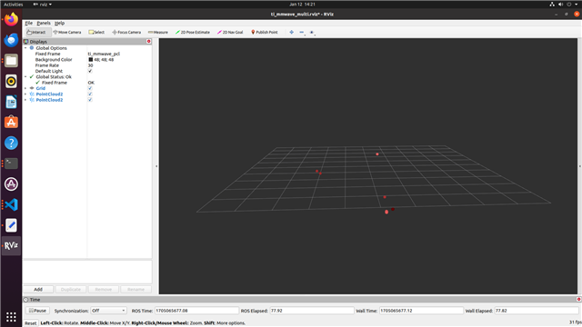
While the point clouds are being published, I am encountering the following two issues:

1. The point clouds are only published when the obstacle or the board is in movement. I would assume this is an defined behaviour and based on the configuration files, but we would like to detect the static surrounding as well and I cannot follow/understand the configuration parameters completely.
2. The parameters are not initialized when I run the ros1driver package using the command: roslaunch ti_mmwave_rospkg 6843_multi_3d_0.launch.

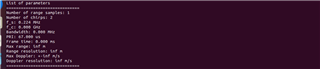
We loaded the default configuration files of 6843_multi_3d.cfg and similiar configs.

We also looked in the issue https://e2e.ti.com/support/sensors-group/sensors/f/sensors-forum/1223354/iwr6843aopevm-lab-resource-example-issue, but this also did not solve the configuration. The values changed with the different position of the incrementation, but most values were inf or 0 most of the times.

I would appreciate any assistance or guidance you can provide to resolve these issues.

Thank you for your help.


Best regards, 

  • Hello,

    By default, the configuration files filter out static points which we call "clutter". If you open the configuration file you are using, you will see a parameter named clutterRemoval enabled. Change the 1 to a 0 to disable clutterRemoval and you will see static points. Also if you are seeing 6843_multi_3d.cfg, you are using an outdated version of the ROS Driver, please download the newest version by cloneing it by doing "git clone https://git.ti.com/git/mmwave_radar/mmwave_ti_ros.git"

    Best Regards,

    Pedrhom

  • Good afternoon,


    Thank you for your kind response. I tested your suggestion, and it worked. Now, I can also see the static points. However, the resolution of the point cloud is really low. I can only see a few points when the radar is in a scene with many objects around and also when the entire surface of the sensor is covered. I'm wondering if there are other parameters to set for better resolution or better stability of the points or if this is the maximum capability of the sensor. In the picture below, you have an example of the points and the environment of the sensor.

    I would also like to have documentation about the significance of the different parameters.


    I would appreciate your assistance again to resolve these issue.


    thank you for your help.


    Best regards,

  • Hello,

    There are many ways to increase detection capability, and have both more points and tighter clusters. One of the simplest first steps is to reduce the CFAR threshold within cfarCfg from 15 to something lower. Think of CFAR as a power/reflectivity threshold that a point must meet in order to be visualized. Lowering the threshold allows more points to meet or exceed said threshold. Other ways include lowering your range resolution of your chirp configuration.

    To help with chirp design, see the mmWave Sensing Estimator

    https://dev.ti.com/gallery/view/mmwave/mmWaveSensingEstimator/ver/2.3.0/

    For information on what each parameter does, see the MMWAVE-SDK's User Guide within its documents folder.

    https://www.ti.com/tool/MMWAVE-SDK

    To see an example of a point cloud with high point quantity with dense clusters, check out the visualization example in the 3D People Track User Guide

    https://dev.ti.com/tirex/explore/node?a=1AslXXD__1.30.01.03&node=A__AJy2dB7pfZ0nJqp9U0xVSg__radar_toolbox__1AslXXD__1.30.01.03

    Best Regards,

    Pedrhom

  • Hello Pedrhom,

    thanks, that already helped.

    The variation of the CFAR threshold parameters led to more points, but not really significantly, so we checked and flashed the other demo.

    When testing the 3D People Track Image with the Industrial Visualizer in Windows we had a much better point cloud for our usage. Unfortunately we were not able to run this flashed image with the ROS driver. Is it possible to run all demos with the ROS driver? The out-of-the-box demo worked fine with the ROS driver.

    We got some communication errors and the ROS driver died after displaying points in RVIZ for a few seconds. I will add the exact error message later.

    We loaded the corresponding AOP_6m_default.cfg config file in the ROS driver. Are there some other configurations, that are different to the Out-of-the-box demo and have to be changed? (e.g. Baudrate or similiar overall settings, that are not set via the .cfg file?

    Our main goal is to develope a detection algorithm on our own implemented in ROS and therefore we would not need too much preprocessing and filtering of the pointcloud beforehand. We just would like to use an image with a rather big pointcloud and publish this one in ROS. 

    If there is no perfect demo image for that, I would assume we have to look into the microcontroller code ourself and adapt the settings and build the image by ourself right? What would be the best basis for that? The 3D People Tracker Demo and then removing/ignoring some of your tracker functionalities?

  • Hello,

    For 6843AOP, use the 3D_people_count_68xx_demo.bin found in mmwave_ti_ros/ros1_driver/src/ti_mmwave_tracker_rospkg/bin/ with launch file AOP_3d_Tracking.launch. They have configuration differences which you compare by opening the launch file in a text editor and then the cfg file in a text editor, and I have mentioned some differences in a thread recently which you can find here.

    I am not sure what your configuration is, but it is possible the sensor is being overloaded. 3D People Tracking binary uses a different algorithm chain which is know as the Capon beamformer methodology as opposed to Out of Box demo's Bartlett methodology. The Capon chain as you have already noticed creates a richer and denser point cloud, but this comes at the cost of computation intensity. When a configuration is set that makes the radar very sensitive, such as having a very low CFAR, and you are also sending information such as tracker and range profile for a very cluttered physical environment, the sensor can be overloaded as information is coming in faster than it can send out which creates a crash.

    So my advice to you is to start with the 3D People Tracking source code, and strip the radar from doing anything except point cloud creation in order to min/max point cloud performance without crashing. You can first try by disabling anything you do not need in the configuration file before touching source code, for example the tracker as it can be disabled by setting a 1 to a 0 in the cfg file which stops it from ever running once started.

    Best Regards,

    Pedrhom