This thread has been locked.

If you have a related question, please click the "Ask a related question" button in the top right corner. The newly created question will be automatically linked to this question.

IWR6843AOP: SPI bootloader to transfer image from TI's CC3220SF Flash into IWR6843 RAM

Part Number: IWR6843AOP
Other Parts Discussed in Thread: CC3220SF, IWR6843, AWR2243, , MMWAVEICBOOST, AWR1642BOOST

Hello Community,

On the custom board, we have IWR6843 connected with CC3220SF for our application.

We want to use just a single FLASH of CC3220SF for both images and on bootup of the board, I want to transfer the radar image into IWR6843 RAM. 

My queries to TI:

1. Is there any example implementation by TI that I could use for this application? This will be helpful and will save a lot of time.

2. If I need to implement protocol by myself, which example should I refer to? How should begin with communication in this case?

3. Which chip will be the SPI Master here? Since communication is initiated by Radar, I think IWR6843 would be the master here. 

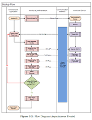
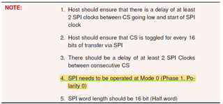
I have referred to the Bootloader flow swra6 for the SPI Bootmode and mmWave-Radar Interface Control document for SPI protocol.

Please let me know more information on this.

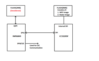
Below is the block diagram of the system we want to implement.

SPIA of IWR6843 MCU is connected with SPI of CC3220SF MCU. SPIB of IWR6843 is pin muxed to be used for I2C communication. 

From one of our custom boards, we have removed the FLASH used by Radar MCU that used QSPI for communication.

Now since FLASH is absent ROM Bootloader will begin SPI bootmode using SPIA for communication to get image.

I need a communication protocol example to implement after this, to transfer the Radar Image from the FLASH of the WiFi chip to the RAM of IWR6843 MCU.


Thanks and Regards,

Swapnil

  • Hello.

    1. Is there any example implementation by TI that I could use for this application? This will be helpful and will save a lot of time.

    I believe there is some source code and documentation on this in SDK 3.6 in the <sdk-install-location>/packages/ti/drivers/qspiflash.  It allows you to access external flash and read/write to serial flash via QSPI.  You can also refer to this E2E for additional information.

    Sincerely,

    Santosh.

  • Hello Santosh,

    Thanks for the reply.

    I have SPIA of IWR6843 connected with WiFi Chip CC3220sf. WiFi chip is connected with its FLASH via its FLASH SPI interface.

    To communicate with the FLASH of the Wi-Fi chip with the QSPI of IWR6843, I will need to connect the IWR6843 QSPI with the WiFI chip FLASH.  Not sure if that would be possible, because of the following reasons:

    1. WiFI chip Flash might not support IWR6843. Its 8MB Flash and is not in the Tested FLASH list of IWR6843

    2. It might affect communication between the WiFi chip and FLASH. 

    Instead, since IWR6843 is connected with a WiFi chip via SPIA, I want to load the Radar image from WiFi FLASH via a WiFi Chip using SPIA into IWR6843 RAM during initialization.

    Hence I need some example code to realize that, or some direction to implement it.

    Thanks and Regards,

    Swapnil

  • Hello Swapnil.

    Outside of the qspiflash driver, I don't think we have any example code of booting over other communication interfaces.  However, we do have some documentation in the mmwavelink doxygen page(for the rlDeviceFileDownload API) that describes how to send the image as packets over SPI to the IWR6843 device.  This is found on page 7 of the bootloader document that you linked.  This E2E also provides information on sample code for another device that could be leveraged for your application.

    Sincerely,

    Santosh

  • Hello Santosh,

    I am referring source code of mmwave_dfp_02_02_04_00 mmWaveLink_SFlash_FW_Example for my use-case. It uses AWR2243 ES 1.0/ES 1.1 boosterpack and DCA1000 EVM and downloads image from PC. This example uses rlDeviceFileDownload API. 

    As per protocol, I have to perform a Bootup event from the Host(External Processor) by calling rlDevicePowerOn initially at step 1.

    The whole setup and example are on the basis that, the mmWave link device is connected to the mmWave Device. But in my case, I have just an external processor connected to the mmWave device.

    The above diagram is from the mmwave Radar Interface document. My question is, in my case, Do I have to reset IWR6843 first, and then as soon as it boots up since it is missing FLASH chip it will raise IRQ and then carry further protocol? 

    The example has APIs for mmwave link application but if I have to implement it on the external processor (CC3220SF), how should I begin with the protocol?

    Thanks and Regards,

    Swapnil

  • Hello Swapnil.

    The above diagram is from the mmwave Radar Interface document. My question is, in my case, Do I have to reset IWR6843 first, and then as soon as it boots up since it is missing FLASH chip it will raise IRQ and then carry further protocol? 

    The device will not have completely finished the boot up process.  During the bootup process, it will check whether flash is present, and since it isn't, it will look to boot up over SPI.  The bootloader will then wait to listen for the bootloader API commands over SPI, which is what the mmWaveLink APIs do as well.  You can refer to those APIs when creating the SPI packets on the external processor on what the payload of the message needs to be.

    My question is, in my case, Do I have to reset IWR6843 first, and then as soon as it boots up since it is missing FLASH chip it will raise IRQ and then carry further protocol? 

    Yes this is correct.  Once the NRESET is sent, it will start the device initialization portion of the bootloader flow and then check if the flash is present, and since it is absent, it will start the bootmode over SPI procedure.  It is at this point that the CC3220SF should do a SPI_write() to send the image in packets defined in the rlDeviceFileDownload.

    The example has APIs for mmwave link application but if I have to implement it on the external processor (CC3220SF), how should I begin with the protocol?

    If you are looking to implement the SPI protocol on the CC3220SF, you will have to ask in the Wireless Connectivity Forum as we do not support those devices.  But the timing and modes of the SPI protocol for the IWR6843 can all be found in the datasheet for the 6843 device in section 8.10.3.  In addition, as I stated earlier, you can refer to the mmWaveLink APIs to determine what is making up the bootloader command and what information has to be sent over SPI from the CC3220SF.  The mmWaveLink APIs are doubling as the bootloader commands in this case, so they will provide the information to build the SPI packet containing the bootloader command that needs to be sent from the host processor to the IWR6843.

    Sincerely,

    Santosh

  • Hello Santosh,

    Thank you for your reply. I am trying to receive SPI HOST INT as soon as I reset  IWR6843.

    Currently, the only way I could reset IWR6843 is by using the debugger with command "xds110reset --action toggle --delay 3000"and then waiting for HOST INT on CC3220. Do you know if it's the correct way to reset to start the SPI Bootloader protocol on IWR6843? 

    I am not getting any interrupt on CC3220SF, so not sure if the IWR6843 has started correctly in SPI boot mode.

    Thanks and Regards,

    Swapnil

  • Hello Swapnil.

    According to the bootloader flow diagram for booting over SPI, you should be looking for an async event called AR_AE_DEV_MSSPOWERUPDONE_SB.  You can find information on the contents of this message in the ICD under AWR_AE_DEV_MSSPOWERUPDONE_SB.

    Currently, the only way I could reset IWR6843 is by using the debugger with command "xds110reset --action toggle --delay 3000"and then waiting for HOST INT on CC3220. Do you know if it's the correct way to reset to start the SPI Bootloader protocol on IWR6843? 

    I believe this is ok.  Just to confirm are you using the ICBoost board when using this reset command?  The IWR6843EVM itself does not have XDS support, but the ICBoost allows for XDS support with the device.  Let me know if you are able to see this message; I don't think you should be looking for an interrupt itself, but this MSSPOWERUPDONE message instead.

    Sincerely,

    Santosh

  • Hello Santosh,

    Yes, I am looking for AR_AE_DEV_MSSPOWERUPDONE_SB, but before that to confirm that IWR is in SPI boot mode, the first thing it does is send IRQ high, and when it's received only then I should send CNYS+Dummy and in response to that IWR will de-assert Host IRQ and then will send AR_AE_DEV_MSSPOWERUPDONE_SB. But I don't have this High IRQ after IWR reset. That's why I am looking into High IRQ.

    I am doing this on a custom board where IWR and WiFi chip are connected via SPIA. No ICBoost board is involved in this process. XDS110 debugger is used to debug IWR chip and I perform reset via this debugger through RESET command. I have checked upon reset and it is performed on IWR, but SPI boot mode is not raising High IRQ.

    Another question, I am using IWR6843AOP where Ball pins for SPIA are

    a. SPIA_MOSI: Ball F2
    b. SPIA_MISO: Ball D1
    c. SPIA_CLK: Ball D2
    d. SPIA_CS_N: Ball C2
    e. SPI_HOST_INTR: Ball B2

    but for IWR6843 which is referred in IWR6843 Bootloader flow, it is

    a. SPIA_MOSI: Ball D13
    b. SPIA_MISO: Ball E14
    c. SPIA_CLK: Ball E13
    d. SPIA_CS_N: Ball E15
    e. SPI_HOST_INTR: Ball P13


    Will this be fine for SPI bootloader? 

    Regards,

    Swapnil

    Regards,

    Swapnil

  • Hello.

    No ICBoost board is involved in this process.

    I believe an ICBoost is needed to perform a device reset if you are going to perform an reset via XDS.  Please try with the ICBoost board and see if you are able to see the IRQ.

    Another question, I am using IWR6843AOP where Ball pins for SPIA are

    a. SPIA_MOSI: Ball F2
    b. SPIA_MISO: Ball D1
    c. SPIA_CLK: Ball D2
    d. SPIA_CS_N: Ball C2
    e. SPI_HOST_INTR: Ball B2

    but for IWR6843 which is referred in IWR6843 Bootloader flow, it is

    a. SPIA_MOSI: Ball D13
    b. SPIA_MISO: Ball E14
    c. SPIA_CLK: Ball E13
    d. SPIA_CS_N: Ball E15
    e. SPI_HOST_INTR: Ball P13

    Let me look into this and provide an update by tomorrow.

    Sincerely,

    Santosh

  • Hello Santosh,

    With direct XDS110 I could toggle NRESET of IWR. I tested this with the logic analyzer. 

    Also, I switched between Functional and Flashing mode by setting SOPs first and then performing NRESET via XDS110 only.

    Regards,

    Swapnil

  • Hello Swapnil.

    I'm a little confused about your setup, as the IWR has no XDS support so it can't interpret the xds command without the ICBoost.  Do you have any other device that is serving as the equivalent of the ICBoost board to be able to interpret the XDS commands?  It would make sense that this isn't working if the device hasn't actually been switched into functional mode as the xds reset isn't working due to the lack of the ICBoost, and since it is still in flashing mode the boot flow hasn't started.  Can you try with an ICBoost to see if it resolves the issue of starting the boot flow?

    Sincerely,

    Santosh

  • Hello Santosh,

    Here is the link about XDS110 where supported devices are mentioned, which also supports 

    • mmWave sensors (IWR/AWR14xx, IWR/AWR16xx, IWR68xx)

    https://software-dl.ti.com/ccs/esd/documents/xdsdebugprobes/emu_xds110.html

    As I mentioned in my previous reply I could switch between Functional and Flashing mode, I could verify from register content on SOP mode register address 0xFFFFE268.

    SOP mode register: FFFF E268 (Flash mode should read 0x00000005, Functional Mode should read 0x00000001)

    This is the contents of my SOP mode register which verifies that the device is in Functional mode.

    Can you please verify with IWR6843AOP ball pins for SPIA which I asked you in previous reply. 

    Regards,

    Swapnil

  • Hello Swapnil.

    Can you please verify with IWR6843AOP ball pins for SPIA which I asked you in previous reply. 

    The pins referenced in the bootloader document are for the IWR6843, which is a different device than the IWR6843AOP, so the pins are different.  Please refer to the ball pins for SPIA in the datasheet for the IWR6843AOP if you are using an AOP device.

    Here is the link about XDS110 where supported devices are mentioned, which also supports 

    • mmWave sensors (IWR/AWR14xx, IWR/AWR16xx, IWR68xx)

    The 6843 devices do support XDS110 but only with the mmWaveICBoost board, as these devices don't have an on-board XDS110, so if you want to use any XDS features you need to have an external XDS device or use the mmWaveICBoost board.  Some of the other devices like the AWR1642Boost and the 1443Boost are EVMs that are designed with an on-board XDS, but the IWR6843AOP does not have this feature.

    This is the contents of my SOP mode register which verifies that the device is in Functional mode.

    This looks correct, but you are probably not resetting the device correctly due to the absence of the mmWaveICBoost.  Can you try using this board and triggering a reset to see if you are then able to see the appropriate signals from the device?

    Sincerely,

    Santosh

  • Hello Santosh,

     If 6843 supports XDS110 only with mmWaveICBoost, then please explain this:

    We have a custom board with IWR6843AOP on it, we debug the board using JTAG XDS110 debugger without using mmWaveICBoost board. 

    Not just that we set up SOPs through the different chip on IWR6843 and when sending the Reset command via XDS110, it switches between Functional and Flashing mode. This we could verify with Register content on SOP mode registers as shown in the previous reply.

    We never used mmWaveICBoost with XDS110 in any process. So how does the debugging working on a custom board?

    Regarding HOST_IRQ high, even if Reset from XDS not working, but still after Power ON reset, HOST_IRQ should remain high until it is acknowledged with SPI message from host. So in the beginning I should see the high signal on this pin in the absence of FLASH.

    Is there any register from where I can know if the device is in SPI boot mode ? 

    Regards,

    Swapnil

  • Hello Swapnil.

    We have a custom board with IWR6843AOP on it, we debug the board using JTAG XDS110 debugger without using mmWaveICBoost board. 

    I was not aware of this detail, so disregard my earlier concerns regarding using the ICBoost board.  If you are using an external JTAG XDS110 debugger then that is ok.  However, it can be a useful tool if you want to confirm the behavior of the reset that you are seeing with your custom setup.

    Regarding HOST_IRQ high, even if Reset from XDS not working, but still after Power ON reset, HOST_IRQ should remain high until it is acknowledged with SPI message from host. So in the beginning I should see the high signal on this pin in the absence of FLASH.

    Is there any register from where I can know if the device is in SPI boot mode ? 

    Looking at the TRM, I did not see any registers that indicated this as flashing and functional modes are the two bootloader modes that are indicated by the registers you mentioned in your previous reply.  Which pin are you looking at to check for the IRQ signal?  Let me look into this some more and see if I can verify that the pin you are looking at is actually where the IRQ signal is sent from, and I will provide an update by the EOD Monday.

    Sincerely,

    Santosh

  • Hello Santosh,

    About the SOP mode register address, I got this information from one of the TI application engineers. I am using IWR6843AOP, where SPI_HOST_INTR is generated from ball pin B2. I am trying to see an interrupt high on this pin as soon as I restart the board or give the Reset command from XDS.

    How long does the ROM bootloader try to communicate with SFLASH when it is absent? And when SFLASH is absent does ROM bootloader still tries to communicate with SFLASH and at the same time activates SPI bootloader as well ?

    Please let me know if I am doing anything wrong here.

    Regards,

    Swapnil

  • Hello Swapnil.

    Looking at the datasheet, the SPI_HOST_INTR pin has its output disabled upon reset and it needs to be pinmuxed to connect the SPI_HOST_INTR signal to the ball B2.  The bootloader flow document lists this as the first step in the document, so I wanted to just confirm that you were doing this as well.  This may be why you are not seeing anything on the pin, as the signal itself is not being routed to the ball that you are reading from.

    Sincerely,

    Santosh

  • Hello Santosh,

    I think I found the problem, we have active low SPIA_nINT on hardware and it is always low when the board starts, which means it is high.

    After SPI initialization on CC3220sf, I write CNYS (SYNC word = 0x5678 0x8765) and Dummy bytes (0xFFFF 0xFFFF
    0xFFFF 0xFFFF 0xFFFF 0xFFFF) on communication channel from CC3220SF, but bootloader never responds by setting SPIA_nINT pin high(HOST IRQ low).

    Looking at the datasheet, the SPI_HOST_INTR pin has its output disabled upon reset and it needs to be pinmuxed to connect the SPI_HOST_INTR signal to the ball B2. 

    I think this is done by the ROM bootloader when it enters into SPI bootloader mode.

    Similar pinmux is done on QSPI communication when Flash is present, but the user doesn't have to do anything there since it is handled by ROM bootloader.

    If I am wrong here, what should be done on the IWR side to Pinmux SPI pins? The SPIA interface is already present on ball pins connected to CC3220SF.

    Regards,

    Swapnil

  • Hello Swapnil.

    If I am wrong here, what should be done on the IWR side to Pinmux SPI pins? The SPIA interface is already present on ball pins connected to CC3220SF.

    You are correct here, I confirmed this myself as well that it is done by the bootloader so no need to do any more pinmuxing.

    After SPI initialization on CC3220sf, I write CNYS (SYNC word = 0x5678 0x8765) and Dummy bytes (0xFFFF 0xFFFF
    0xFFFF 0xFFFF 0xFFFF 0xFFFF) on communication channel from CC3220SF, but bootloader never responds by setting SPIA_nINT pin high(HOST IRQ low).

    This behavior makes sense if the pin is active low.  It would indicate that the bootloader flow on the device has checked for flash, not found it, and as a result, sent out this IRQ signal to the mmwavelink device(the WIFI device), and now you can send the contents to the RAM on the IWR6843.  I just want to understand what you are expecting to see with this dummy command, and if you have tried sending the actual bootloader command.

    Sincerely,

    Santosh

  • Hello Santosh,

    According to protocol, when HOST IRQ goes high, then Host has to write (SYNC word = 0x5678 0x8765) and Dummy bytes (0xFFFF 0xFFFF
    0xFFFF 0xFFFF 0xFFFF 0xFFFF) on the communication channel, you can see this on section 3.2.1 Command/Response Sequence (Host) and also mentioned in the flow diagram shown in the figure attached in my previous reply. 

    Later once this SYNC word with Dummy bytes is sent HOST IRQ will go Low and then power up event will be written from IWR to HOST(WiFi chip).

    You can refer to the protocol.


    Regards,

    Swapnil

  • Hello Swapnil.

    Apologies for the confusion, I was still referring to the bootloader flow document and referring to the steps in the rlDeviceFileDownload API as opposed to the flow diagram you referenced.  Let me look into this as I thought you could start sending the file contents once you received the AR_AE_DEV_MSSPOWERUPDONE_SB Async event.  You may also want to make sure that the SPI message sent from the wifi chip is matching the SPI specifications, for both timing and payload formatting, of the IWR device, which can be found in the IWR6843 datasheet.

    Sincerely,

    Santosh

  • Hello Santosh,

    Here is the SPI Initialization for WiFi Chip:

    /* Open SPI as Master */
    SPI_Params_init(&spiParams);
    spiParams.frameFormat = SPI_POL0_PHA1;
    spiParams.bitRate = 10000000;
    spiParams.dataSize = 16;
    spiParams.transferTimeout = 80000; // 1ms
    spiParams.mode = SPI_MASTER;

    and this is what I am trying to send when HIGH_IRQ is there

    SPITxBuffer[0] = 0x5678U;
    SPITxBuffer[1] = 0x8765U;
    SPITxBuffer[2] = 0xFFFFU;
    SPITxBuffer[3] = 0xFFFFU;
    SPITxBuffer[4] = 0xFFFFU;
    SPITxBuffer[5] = 0xFFFFU;
    SPITxBuffer[6] = 0xFFFFU;
    SPITxBuffer[7] = 0xFFFFU;

    In the attached diagram you will find the CNYS + Dummy data I sent to IWR when HOST_IRQ was high

    Note: I could not set a sampling rate higher than 50MHz in the logic analyzer, that's why the data doesn't look sharp.

    These are the following measures for SPI settings:

    1. The host should ensure that there is a delay of at least 2 SPI clocks between CS going low and the start of the SPI clock.

    2. The host should ensure that CS is toggled for every 16 bits of transfer via SPI

    3. There should be a delay of at least 2 SPI Clocks between consecutive CS

    4. SPI needs to be operated at Mode 0 (Phase 1, Polarity 0)

    5. SPI word length should be 16-bit (Half word)

    Please let me know if it's correct.

    How important is the 1st SPI requirement?, because when nCS goes low at the same time SPI CLK starts, there is no 2 CLK delay between CS and CLK.

    With SPI settings in CC3220SF it is not possible to set such delay between CS and CLK.

    Can you please ask your team, how important is this requirement? 

     Regards,

    Swapnil

  • Hello Swapnil.

    I think this 1st requirement is important because it messes up the timing on the SPI transmission.  Also were you able to confirm that the message is being sent in the correct order and the endianness is correct?  Its a bit difficult to tell based off the screenshot so I just wanted to confirm.  Its possible because of the incorrect timing that the message is being interpreted incorrectly, so one thing you can try is reducing the bit rate of the spiParams to 5 MHz instead of 10.

    Sincerely,

    Santosh

  • Hello Santosh,

    By default, CC3220SF has MSB first during SPI transmission. So I think endianness is correct. 

    I tried 100Khz just for the experiment and 1MHz yesterday and it is the same behavior, I could try 5MHz, but I think the result will be the same.

    This is the image with the 1MHz clock:

    From this image, you can interpret the data I am sending via SPI.

    Regards,

    Swapnil

  • Hello Santosh,

    I have a couple of things to ask:

    1. About the SPI requirement, "The host should ensure that there is a delay of at least 2 SPI clocks between CS going low and the start of the SPI clock", as per the IWR6843AOP datasheet, this is a general requirement of SPI, it is mentioned in IWR6843AOP datasheet section 8.10.5.4 Typical Interface Protocol Diagram (Peripheral Mode).

    We have been using SPI communication between IWR6843AOP and CC3220SF without fulfilling this requirement to transfer Radar Data to WiFi Chip. So I think it's not necessary SPI boot process as well, but can you please confirm this from your developer colleagues?

    2. As we discussed about bringing the mmWave device out of reset during the initial process of SPI boot, below is the function that is called upon calling rlDevicePowerOn():

    /** @fn int rlsEnableDevice(unsigned char deviceIndex)
    *
    *   @brief This function enables the device having the specified device index
    *   @param[in] deviceIndex - Index of the device that needs to be enabled
    *
    *   @return int Success - RLS_RET_CODE_OK,
    *               Failure - RLS_RET_CODE_NULL_PTR_ERROR
    */
    int rlsEnableDevice( unsigned char deviceIndex )
    {
        rlsDevCtx_t*    pDevCtx;
        int             retVal = RLS_RET_CODE_OK;
    
        DEBUG_PRINT("Enable Device\n");
    
    #ifndef RLS_SPI_SIMULATION
        pDevCtx = (rlsDevCtx_t *)rlsGetDeviceCtx(deviceIndex);
    
        if(NULL != pDevCtx)
        {
            pDevCtx->deviceEnabled = TRUE;
            /* Starting Interrupt Thread after Power on to avoid Spurious Interrupt */
            if (NULL != pDevCtx->hostIntrThread.handler)
            {
                rlsStartIrqPollingThread(pDevCtx);
            }
        }
        else
        {
            retVal = RLS_RET_CODE_NULL_PTR_ERROR;
        }
    #endif
        return retVal;
    }

     This function only initializes IRQ Polling task, and there is no mmWave out-of-reset functionality. This means it's only applicable if you want to register a task to receive IRQ interrupts. But since we already have IRQ interrupt handler we don't need this.

    So can we start SPI boot process without calling rlDevicePowerOn()?  because we don't want to use redundant functionality to reduce code size.

    Regards,

    Swapnil

  • Hello Swapnil.

    We have been using SPI communication between IWR6843AOP and CC3220SF without fulfilling this requirement to transfer Radar Data to WiFi Chip. So I think it's not necessary SPI boot process as well, but can you please confirm this from your developer colleagues?

    I believe this timing requirement is important because the SPI is configured by the bootloader in this situation, while in the other situations, I assume that you are configuring the SPI channels, so the bootloader flow may require this timing requirement to be met.  I am looking to confirm this, but I believe this may be a potential issue.

    So can we start SPI boot process without calling rlDevicePowerOn()?  because we don't want to use redundant functionality to reduce code size.

    The code snippet you provided was for rlEnableDevice and not rlDevicePowerOn().  I would recommend using rlDevicePowerOn to bring the device out of reset to trigger the host IRQ signal.  One thing that would be helpful is if you could include a snapshot of the readings on the SPI channel, specifically the interrupt signal before and after the reset occurs, along with the timing information.  It seems odd that you are seeing no change in behavior on the INT pin after the XDS reset occurs, and I believe that regardless of the polarity of the pin, the value of the pin should be high when the message is ready to be received.

    Sincerely,

    Santosh

  • Hello Santosh.

    The code snippet you provided was for rlEnableDevice and not rlDevicePowerOn().  I would recommend using rlDevicePowerOn to bring the device out of reset to trigger the host IRQ signal.

    Regarding rlDevicePowerOn(), I mentioned only the rlEnableDevice() function because this is the last call back in rlDevicePowerOn(). Below is the code snippet of the rlDevicePowerOn() function, where a callback for rlEnableDevice() is mentioned. None of the sequences brings mmWave out of reset. There is MMWL_ResetDevice(), which provides a warm reset to the device before calling MMWL_powerOnMaster() in the main code but rlDevicePowerOn() does not perform any reset and does not bring mmWave out of reset.

    Also, MMWL_ResetDevice() performs warm reset through mmWave GPIO connected with FTDI. With the SPI interface, it's not possible. You can go through the code you have provided me and that does not make sense when I am not using the FTDI interface but just the SPI interface.

    I know later in the process SPI communication happens through FTDI but before that GPIOs are used through FTDI to perform the initial process.

    So my question is do need to provide this reset?  or I can go ahead with SPI protocol as soon as the device starts.

    /** @fn rlReturnVal_t rlDevicePowerOn(rlUInt8_t deviceMap, rlClientCbs_t clientCb)
    *
    *   @brief Bring mmwave Device Out of Reset
    *   @param[in] deviceMap - bitmap of all the connected Device
    *   @param[in] clientCb - Client Callbacks for OS/SPI/Interrupts etc
    *
    *   @return rlReturnVal_t Success - 0, Failure - Error Code
    *
    *   Bring mmwave Device Out of Reset. Application should wait for async event of
    *   subBlock RL_DEV_AE_MSSPOWERUPDONE_SB (in case of AWR1243) before issuing any other APIs
    */
    /* DesignId : MMWL_DesignId_004 */
    /* Requirements : AUTORADAR_REQ-707 */
    rlReturnVal_t rlDevicePowerOn(rlUInt8_t deviceMap, rlClientCbs_t clientCb)
    {
        rlReturnVal_t retVal;
        rlUInt8_t index = 0U;
        /* get rlDriver global structure pointer */
        rlDriverData_t *rlDrvData = rlDriverGetHandle();
    
        /* if driver is already initialized */
        if ((rlDrvData != NULL) && (rlDrvData->isDriverInitialized == 1U))
        {
            /* DeInitialize Device */
            retVal = rlDevicePowerOff();
        }
        else
        {
            retVal = RL_RET_CODE_OK;
        }
    
        /* if there is no error found from above conditioning then go ahead and poweron
            mmwavelink & device */
        if (retVal == RL_RET_CODE_OK)
        {
            /* Initialize Host Communication Protocol Driver */
            if (rlDriverInit(deviceMap, clientCb) < 0)
            {
                /* if driver Init failed then set return error code */
                retVal += RL_RET_CODE_RADAR_IF_ERROR;
            }
            else
            {
                /* Power up mmwave Device */
                do
                {
                    /* loop for all devices connected to device/Host */
                    if ((deviceMap & (1U << index)) != 0U)
                    {
                        /* Enable the 12xx device where it will power up the device and read
                            first Async Event */
                        if (clientCb.devCtrlCb.rlDeviceEnable(index) < 0)
                        {
                            /* set return error code */
                            retVal += RL_RET_CODE_RADAR_IF_ERROR;
                            RL_LOGE_ARG0("mmWaveLink: Enabling device failed \n");
                            /* if device enable is failed the de-init mmwavelink driver */
                            (void)rlDriverDeInit();
                            RL_LOGW_ARG0("mmWaveLink Driver DeInit done\n");
                        }
                        /* Reset device Index in DeviceMap for which device has been enabled */
                        deviceMap &= ~(1U << index);
                    }
                    /* increment device index */
                    index++;
                }
                while ((deviceMap != 0U) && (index < RL_DEVICE_CONNECTED_MAX));
            }
        }
        RL_LOGV_ARG0("mmWaveLink Power Up completes\n");
    
        return retVal;
    }
    
    /** @fn int rlsEnableDevice(unsigned char deviceIndex)
    *
    *   @brief This function enables the device having the specified device index
    *   @param[in] deviceIndex - Index of the device that needs to be enabled
    *
    *   @return int Success - RLS_RET_CODE_OK,
    *               Failure - RLS_RET_CODE_NULL_PTR_ERROR
    */
    int rlsEnableDevice( unsigned char deviceIndex )
    {
        rlsDevCtx_t*    pDevCtx;
        int             retVal = RLS_RET_CODE_OK;
    
        DEBUG_PRINT("Enable Device\n");
    
    #ifndef RLS_SPI_SIMULATION
        pDevCtx = (rlsDevCtx_t *)rlsGetDeviceCtx(deviceIndex);
    
        if(NULL != pDevCtx)
        {
            pDevCtx->deviceEnabled = TRUE;
            /* Starting Interrupt Thread after Power on to avoid Spurious Interrupt */
            if (NULL != pDevCtx->hostIntrThread.handler)
            {
                rlsStartIrqPollingThread(pDevCtx);
            }
        }
        else
        {
            retVal = RLS_RET_CODE_NULL_PTR_ERROR;
        }
    #endif
        return retVal;
    }

    Regards,
    Swapnil

  • Hello Santosh.

    As you asked for the HOST_nIRQ line before and after the XDS reset, it remains low for the complete time.

    The measurement is done with 1MHz SPI CLK

    here is the diagram

    The HOST_nIRQ (active low) should go high after sending this command when recognized by the SPI bootloader and then later should send R_AE_DEV_MSSPOWERUPDONE_SB message.

    One discrepancy that I found in mmWave Radar Interface document section 3.2.4 SPI Message Sequence – Command/Response:

    Page 19

    The highlighted point 4 says SPI needs to be operated in Mode 0(Phase 1, Polarity 0), but Phase 1, Polarity 0 is in SPI Mode 1 not in 0.

    So SPI should be operated in Mode 0 or Mode 1?

    Regards,
    Swapnil

  • Hello Swapnil.

    It looks like it is going high for a little bit before going back to low.  Let me check if this is the intended behavior.  Are those little peaks indicating when you are pressing the reset?

    I believe this timing requirement is important because the SPI is configured by the bootloader in this situation, while in the other situations, I assume that you are configuring the SPI channels, so the bootloader flow may require this timing requirement to be met.  I am looking to confirm this, but I believe this may be a potential issue.

    In addition, to follow up on this, this timing requirement is mandatory because this is something that is configured by the RBL and cannot be changed, so you must meet this requirement from the host side to be able to send over the messages and have it interpreted by the radar device.

    The highlighted point 4 says SPI needs to be operated in Mode 0(Phase 1, Polarity 0), but Phase 1, Polarity 0 is in SPI Mode 1 not in 0.

    So SPI should be operated in Mode 0 or Mode 1?

    Whichever mode on that device that has phase 1, polarity 0 is the mode that needs to be used for transmitting SPI messages from the host.  If that is SPI mode 1 on the CC3220SF chip, then you will need to use SPI mode 1.  The SPI on the IWR device is set up by the bootloader, so it cannot be changed.

    Sincerely,

    Santosh

  • Hello Santosh,

    Are those little peaks indicating when you are pressing the reset?

    These are just the noise signals on HOST_nIRQ. The reset comes much before this communication.

    Regards,

    Swapnil

  • Closing thread as discussion has moved offline