This thread has been locked.

If you have a related question, please click the "Ask a related question" button in the top right corner. The newly created question will be automatically linked to this question.

AWR2944: Doubts about rawdata data parsing for mmwave studio 03.01.01.00 acquisition of AWR2944 + DCA1000

Part Number: AWR2944
Other Parts Discussed in Thread: AWR1642, UNIFLASH, STRIKE, IWR1843

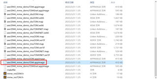
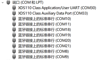
Hi,I've recently tried to capture raw data on mmwave studio 03.01.01.00 using AWR2944+DCA1000, but I'm a bit confused about the data format. I am now able to successfully connect the AWR2944+DCA1000 to my computer and I can see the [Record 2.8] logo. But I am still confused about the format of the collected data.

Doubt 1: Since mmwave studio 03.01.01.00 only supports single real samples, each received ADC data (i.e. LVDS data all the way) is actually data all the way to the RX, is there any problem for me to understand it this way?

Doubt 2: I know very well how to set the TDM mode of the sender in mmwavestudio 02.01.01.00, and I set it in the same way in mmwave studio 03.01.01.00, but it doesn't seem to work.

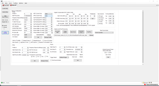
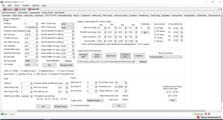
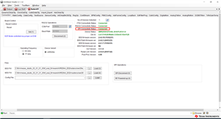
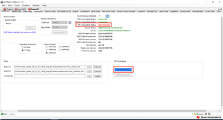
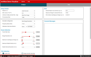
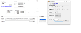
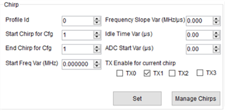
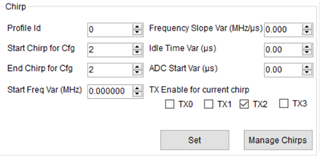
The way I have it set up for sensor config is as follows:

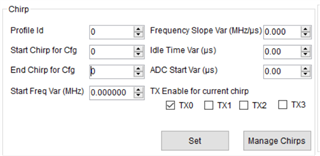
Here's how I set it up in Frame:

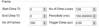
That means I'm set up for 3 transmitters and 4 receivers, with 3 transmitter antennas transmitting in TDM.

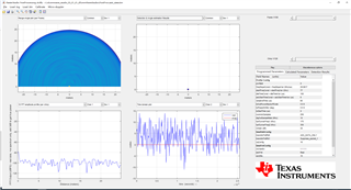
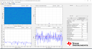
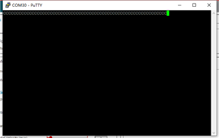
But I end up getting incorrect results after PostProc, I placed a strong reflector (a large iron plate) 1.5m in front of the radar, but the result graph shows nothing, did I set it up wrong somewhere?

AWR2944+DCA1000:

Object to be tested, large iron plate:

The resulting graph after clicking PostProc:

I was shocked at the final result of the Range-Doppler plot being empty, and wondered what had gone wrong, please help with the answer, thank you!

  • Hi,

    I recommend that you try first 1Tx to make sure that the data capture process works fine

    thank you

    Cesar

  • Thanks for the reply, my configuration is as follows:

    I set it up for a 1-TX 4-RX mode.The final result of clicking PostProc is as follows:

    As you can see, there are still no results, no human body detected, but the fact that I'm 1m in front of the radar. It looks like it should be caused by the lack of power on the transmitter side and all that is received is the bottom noise. I don't know why this is, please also answer, thank you!

    PS1:I am now able to generate the adc.bin file with a file size of 25600KB = 256*128*4*16bit*100/1024/8bit without any problem.

    PS2:And I have a doubt, how can I distinguish the phase difference when the received data are all real numbers? This will directly affect the angle measurement.

    PS3:I found that it seems like mmwave studio 03_01_01_00 only works with AWR 2944 ES2.0 version, while my own AWR 2944 board is ES1.0 version (because I bought it before March 2023, and I read in other threads that AWR2944 ES2.0 has only been released since March 2023), is there any way to capture rawdata of AWR2944 ES version 1.0 via mmwave studio?

  • Hi,

    Thanks a lot for your patience. Please find my responses to your questions as follows:

    1. I am now able to generate the adc.bin file with a file size of 25600KB = 256*128*4*16bit*100/1024/8bit without any problem. -> Would it be possible to share your output log to see all the configurations you have set and the sequence in which you have done so? On first look, are there any configs missed when compared to running TI provided .lua scripts for configuration and capture?
    2. And I have a doubt, how can I distinguish the phase difference when the received data are all real numbers? This will directly affect the angle measurement. -> Once you apply a frequency domain transform using FFT, you should be able to obtain the phase for each component and the samples will be complex.
    3. I found that it seems like mmwave studio 03_01_01_00 only works with AWR 2944 ES2.0 version, while my own AWR 2944 board is ES1.0 version (because I bought it before March 2023, and I read in other threads that AWR2944 ES2.0 has only been released since March 2023), is there any way to capture rawdata of AWR2944 ES version 1.0 via mmwave studio? -> You can use the Studio CLI tool for the capture which should be available on the TI resource explorer.

    Regards,

    Kaushik

  • Thank you very much for your reply, and I apologize for being a little slow to respond to some things over the past few days.
    1. this is my output log

    GM: Constructor
    GM: Tue Feb 06 00:45:04 2024
    RSTD.Transmit("/Settings")
    [00:45:05]
    [00:45:05] ### Running Startup script: "C:\ti\mmwave_studio_03_01_01_00\mmWaveStudio\Scripts\Startup.lua" ###
    [00:45:05] RSTD.SetAndTransmit ("/Settings/Scripter/Display DateTime" , "1")
    [00:45:05] RSTD.SetAndTransmit ("/Settings/Scripter/DateTime Format" , "HH:mm:ss")
    [00:45:05] Scripter ignored: Attempt to UnBuild() again or before Build.
    [00:45:05] RSTD.SetVar ("/Settings/Clients/Client 0/Dll" , "C:\\ti\\mmwave_studio_03_01_01_00\\mmWaveStudio\\Clients\\\\LabClient.dll")
    [00:45:05] RSTD.SetVar ("/Settings/Clients/Client 0/Use" , "TRUE")
    [00:45:05] RSTD.SetVar ("/Settings/Clients/Client 1/Use" , "FALSE")
    [00:45:05] RSTD.SetVar ("/Settings/Clients/Client 2/Use" , "FALSE")
    [00:45:05] RSTD.SetVar ("/Settings/Clients/Client 3/Use" , "FALSE")
    [00:45:05] RSTD.SetVar ("/Settings/Clients/Client 4/Use" , "FALSE")
    [00:45:05] RSTD.SetVar ("/Settings/AL Client/AL Dll" , "C:\\ti\\mmwave_studio_03_01_01_00\\mmWaveStudio\\RunTime\\SAL.dll")
    [00:45:05] RSTD.SetVar ("/Settings/Clients/Client 0/GuiDll" , "")
    [00:45:05] RSTD.SetVar ("/Settings/AutoUpdate/Enabled" , "TRUE")
    [00:45:05] RSTD.SetVar ("/Settings/AutoUpdate/Interval" , "1")
    [00:45:05] RSTD.SetVar ("/Settings/Monitors/UpdateDisplay" , "TRUE")
    [00:45:05] RSTD.SetVar ("/Settings/Monitors/OneClickStart" , "TRUE")
    [00:45:05] RSTD.SetVar ("/Settings/Automation/Automation Mode" , "false")
    [00:45:05] RSTD.Transmit("/")
    [00:45:05] RSTD.SaveSettings(): Settings saved to "C:\Users\ASUS\AppData\Roaming\RSTD\config.xml"
    [00:45:05] RSTD.Build()
    [00:45:05] RSTD.SaveSettings(): Settings saved to "C:\Users\ASUS\AppData\Roaming\RSTD\config.xml"
    [00:45:05] RSTD.Transmit("/")
    [00:45:05] RSTD.AL_Build()
    [00:45:05] RSTD.AL_LoadXml()
    [00:45:05] RSTD.Transmit("/")
    [00:45:05] RSTD.AL_Init()
    [00:45:05] RSTD.Clients_Build()
    [00:45:05] GM: Init
    [00:45:05] GM: Loaded 'C:\ti\mmwave_studio_03_01_01_00\mmWaveStudio\Clients\\LabClient.dll'
    [00:45:05] GM: 1 Guest (s) init
    [00:45:05] GM: 1 Module(s) init
    [00:45:05] GM: 2 Tab (s) init
    [00:45:05] RSTD.Client_LoadXml()
    [00:45:06] [RadarAPI]: ar1.GuiVersion()
    [00:45:06] [RadarAPI]: ar1.selectRadarMode(0)
    [00:45:06] [RadarAPI]: Status: Passed
    [00:45:06] Matlab Runtime Engine is installed
    [00:45:06] [RadarAPI]: Starting Matlab Engine..
    [00:45:23] [RadarAPI]: Matlab Engine Started!
    [00:45:24] [RadarAPI]: ar1.selectCascadeMode(0)
    [00:45:24] [RadarAPI]: Status: Passed
    [00:45:24] [RadarAPI]: ar1.LoadSettings('C:\Users\ASUS\AppData\Roaming\RSTD\ar1gui.ini')
    [00:45:25] TESTING = false
    [00:45:25] RstdNet: Port 2777: Listening..
    [00:45:25]
    [00:45:25] ***Script completed successfully.***
    [00:45:27] [RadarAPI]: Opening Gpio Control Port()
    [00:45:27] [RadarAPI]: Status: Passed
    [00:45:27] [RadarAPI]: Opening Board Control Port()
    [00:45:27] [RadarAPI]: Status: Passed
    [00:45:28] [RadarAPI]: ar1.FullReset()
    [00:45:28] [RadarAPI]: Status: Passed
    [00:45:29] [RadarAPI]: Closing Board Control Port()
    [00:45:29] [RadarAPI]: Status: Passed
    [00:45:29] [RadarAPI]: Closing Gpio Control Port()
    [00:45:29] [RadarAPI]: Status: Passed
    [00:45:29] [RadarAPI]: ar1.SOPControl(2)
    [00:45:29] [RadarAPI]: Status: Passed
    [00:45:30] [RadarAPI]: ar1.Connect(38,921600,1000)
    [00:45:32] [RadarAPI]: Warning: Connected with baudrate 115200
    [00:45:33] [RadarAPI]: Warning: Disconnected existing BaudRate
    [00:45:34] [RadarAPI]: Warning: Trying to connect with baudrate 921600
    [00:45:35] [RadarAPI]: ar1.Calling_IsConnected()
    [00:45:36] [RadarAPI]: Part number of the device = 0x98
    [00:45:36] [RadarAPI]: Device type = GP
    [00:45:36] [RadarAPI]: ar1.SelectChipVersion("AR1642")
    [00:45:36] [RadarAPI]: Status: Passed
    [00:45:36] [RadarAPI]: ar1.deviceVariantSelection("XWR2944")
    [00:45:36] [RadarAPI]: Status: Passed
    [00:45:36] [RadarAPI]: ar1.frequencyBandSelection("77G")
    [00:45:36] [RadarAPI]: ar1.SelectChipVersion("AWR2944")
    [00:45:36] [RadarAPI]: Status: Passed
    [00:45:36] Device Status : AWR2944/GP/ASIL-B/SOP:2/ES:1.0
    [00:45:36] [RadarAPI]: ar1.SaveSettings('C:\Users\ASUS\AppData\Roaming\RSTD\ar1gui.ini')
    [00:46:10] [RadarAPI]: ar1.DownloadBSSFw("C:\\ti\\mmwave_studio_03_01_01_00\\rf_eval_firmware\\AWR2944_ES2\\radarss\\xwr29xx_radarss.bin")
    [00:46:14] [RadarAPI]: ar1.GetBSSFwVersion()
    [00:46:14] [RadarAPI]: BSSFwVersion:(02.04.00.18 (15/02/21))
    [00:46:15] [RadarAPI]: ar1.GetBSSPatchFwVersion()
    [00:46:15] [RadarAPI]: BSSPatchFwVersion:(02.04.08.03 (24/03/23))
    [00:46:15] [RadarAPI]: ar1.DownloadMSSFw("C:\\ti\\mmwave_studio_03_01_01_00\\rf_eval_firmware\\AWR2944_ES2\\masterss\\xwr29xx_masterss.bin")
    [00:46:18] [RadarAPI]: Downloading MSS RPRC Binary..
    [00:46:22] [RadarAPI]: ar1.GetMSSFwVersion()
    [00:46:22] [RadarAPI]: MSSFwVersion:(02.04.01.07 (15/02/23))
    [00:46:23] [RadarAPI]: ar1.PowerOn(0, 1000, 0, 0)
    [00:46:23] [RadarAPI]: Status: Passed
    [00:46:23] MSS power up done async event received!
    [00:46:25] [RadarAPI]: ar1.RfEnable()
    [00:46:26] BSS power up done async event received!
    [00:46:26] [RadarAPI]: Status: Passed
    [00:46:26] [RadarAPI]: ar1.GetMSSFwVersion()
    [00:46:26] [RadarAPI]: MSSFwVersion:(02.04.01.07 (15/02/23))
    [00:46:26] [RadarAPI]: ar1.GetBSSFwVersion()
    [00:46:26] [RadarAPI]: BSSFwVersion:(02.04.00.18 (15/02/21))
    [00:46:27] [RadarAPI]: ar1.GetBSSPatchFwVersion()
    [00:46:27] [RadarAPI]: BSSPatchFwVersion:(02.04.08.03 (24/03/23))
    [00:46:36] [RadarAPI]: ar1.ChanNAdcConfig(1, 1, 1, 1, 1, 1, 1, 1, 2, 0, 0)
    [00:46:36] [RadarAPI]: Status: Passed
    [00:46:37] [RadarAPI]: ar1.LPModConfig(0, 0)
    [00:46:37] [RadarAPI]: Status: Passed
    [00:46:38] [RadarAPI]: ar1.RfInit()
    [00:46:38] RF Init async event received!
    [00:46:38] [RadarAPI]: Time stamp, Temperture: 12610,45; SynthVCO3 Status, Update: 0, 0; APLL Status, Update: 1, 1; SynthVCO1 Status, Update: 0, 0; SynthVCO2 Status, Update: 0, 0; LODist Status, Update: 0, 0; RxADCDC Status, Update: 1, 1; HPFcutoff Status, Update: 0, 0; LPFcutoff Status, Update: 1, 1; PeakDetector Status, Update: 0, 0; TxPower Status, Update: 0, 0; RxGain Status, Update: 0, 0; TxPhase Status, Update: 1, 1; RxIQMM Status, Update: 0, 0;
    [00:46:38] [RadarAPI]: Status: Passed
    [00:46:42] [RadarAPI]: ar1.DataPathConfig(513, 1216644097, 0)
    [00:46:42] [RadarAPI]: Status: Passed
    [00:46:43] [RadarAPI]: ar1.LvdsClkConfig(1, 1)
    [00:46:43] [RadarAPI]: Status: Passed
    [00:46:44] [RadarAPI]: ar1.LVDSLaneConfig(0, 1, 1, 0, 0, 1, 0, 0)
    [00:46:44] [RadarAPI]: Status: Passed
    [00:46:52] [RadarAPI]: ar1.ProfileConfig(0, 77, 100, 6, 60, 0, 0, 0, 0, 0, 0, 0, 0, 29.982, 0, 256, 10000, 2216755200, 0, 30, 0, 0, 0)
    [00:46:52] [RadarAPI]: Status: Passed
    [00:46:57] [RadarAPI]: ar1.ChirpConfig(0, 0, 0, 0, 0, 0, 0, 1, 1, 0, 0)
    [00:46:57] [RadarAPI]: Status: Passed
    [00:46:57] Test Source Already Disabled...!!!
    [00:46:57] [RadarAPI]: ar1.DisableTestSource(0)
    [00:46:57] [RadarAPI]: Status: Passed
    [00:46:58] [RadarAPI]: ar1.FrameConfig(0, 0, 8, 128, 40, 0, 1)
    [00:46:58] [RadarAPI]: Status: Passed
    [00:47:00] [RadarAPI]: ar1.GetCaptureCardDllVersion()
    [00:47:00] [RadarAPI]: Sending dll_version command to DCA1000
    [00:47:00] [RadarAPI]:
    [00:47:00] DLL Version : 1.0
    [00:47:00] [RadarAPI]: ar1.SelectCaptureDevice("DCA1000")
    [00:47:00] [RadarAPI]: Status: Passed
    [00:47:01] [RadarAPI]: ar1.CaptureCardConfig_EthInit("192.168.33.30", "192.168.33.180", "12:34:56:78:90:12", 4096, 4098)
    [00:47:01] [RadarAPI]: ar1.CaptureCardConfig_Mode(1, 2, 1, 2, 3, 30)
    [00:47:01] [RadarAPI]: ar1.CaptureCardConfig_PacketDelay(25)
    [00:47:01] [RadarAPI]: Sending fpga command to DCA1000
    [00:47:11] [RadarAPI]:
    [00:47:11] FPGA Configuration :
    [00:47:11] Timeout Error! System disconnected
    [00:47:11] [RadarAPI]: Sending record command to DCA1000
    [00:47:19] [RadarAPI]: ar1.CaptureCardConfig_EthInit("192.168.33.30", "192.168.33.180", "12:34:56:78:90:12", 4096, 4098)
    [00:47:19] [RadarAPI]: ar1.CaptureCardConfig_Mode(1, 2, 1, 2, 3, 30)
    [00:47:19] [RadarAPI]: ar1.CaptureCardConfig_PacketDelay(25)
    [00:47:19] [RadarAPI]: Sending fpga command to DCA1000
    [00:47:19] [RadarAPI]:
    [00:47:19]
    [00:47:19] ConnectRFDCCard_ConfigMode(): Bind failed (Config port) : 10048
    [00:47:19] Ethernet connection failed. [error -4051]
    [00:47:19] [RadarAPI]: Sending record command to DCA1000
    [00:47:19] [RadarAPI]:
    [00:47:19]
    [00:47:19] ConnectRFDCCard_ConfigMode(): Bind failed (Config port) : 10048
    [00:47:19] Ethernet connection failed. [error -4051]
    [00:47:19] [RadarAPI]: ar1.GetCaptureCardFPGAVersion()
    [00:47:19] [RadarAPI]: Sending fpga_version command to DCA1000
    [00:47:19] [RadarAPI]:
    [00:47:19]
    [00:47:19] ConnectRFDCCard_ConfigMode(): Bind failed (Config port) : 10048
    [00:47:19] Ethernet connection failed. [error -4051]
    [00:47:22] [RadarAPI]:
    [00:47:22] Configure Record :
    [00:47:22] Timeout Error! System disconnected
    [00:47:22] [RadarAPI]: ar1.GetCaptureCardFPGAVersion()
    [00:47:22] [RadarAPI]: Sending fpga_version command to DCA1000
    [00:47:22] [RadarAPI]:
    [00:47:22]
    [00:47:22] FPGA Version : 2.8 [Record]
    [00:47:22]
    [00:47:27] [RadarAPI]: ar1.CaptureCardConfig_EthInit("192.168.33.30", "192.168.33.180", "12:34:56:78:90:12", 4096, 4098)
    [00:47:27] [RadarAPI]: ar1.CaptureCardConfig_Mode(1, 2, 1, 2, 3, 30)
    [00:47:27] [RadarAPI]: ar1.CaptureCardConfig_PacketDelay(25)
    [00:47:27] [RadarAPI]: Sending fpga command to DCA1000
    [00:47:27] [RadarAPI]:
    [00:47:27] FPGA Configuration command : Success
    [00:47:27] [RadarAPI]: Sending record command to DCA1000
    [00:47:28] [RadarAPI]:
    [00:47:28] Configure Record command : Success
    [00:47:28] [RadarAPI]: ar1.GetCaptureCardFPGAVersion()
    [00:47:28] [RadarAPI]: Sending fpga_version command to DCA1000
    [00:47:28] [RadarAPI]:
    [00:47:28]
    [00:47:28] FPGA Version : 2.8 [Record]
    [00:47:28]
    [00:47:31] [RadarAPI]: ar1.CaptureCardConfig_StartRecord("C:\\ti\\mmwave_studio_03_01_01_00\\mmWaveStudio\\PostProc\\adc_data.bin", 1)
    [00:47:31] [RadarAPI]: Sending start_record command to DCA1000
    [00:47:32] [RadarAPI]: ar1.StartFrame()
    [00:47:32] [RadarAPI]: Status: Passed
    [00:47:32] Frame start async event received!
    [00:47:32] Frame End async event received!
    [00:47:32] [RadarAPI]: Frame Ended
    [00:47:34] [RadarAPI]:
    [00:47:34] Start Record command : Success
    [00:47:34]
    [00:47:34] Record is completed
    [00:47:34]
    [00:47:34] Record stop is done successfully
    [00:47:34] [RadarAPI]:
    [00:47:37] [RadarAPI]: ar1.StartMatlabPostProc("C:\\ti\\mmwave_studio_03_01_01_00\\mmWaveStudio\\PostProc\\adc_data.bin")
    [00:47:37] [RadarAPI]: No of files Captured: 1, Total no of frames for each device : 8

    2. thanks, i understand
    3. i'm not quite sure how to get the raw ADC data from AWR2944 ES1.0 using mmwave studio CLI. is there any tutorial i can refer to?
    Again, I apologize for the delay.

  • Hi,

    Thank you very much for your feedback with more details. Please find my responses as below:

    1. The sequence here seems okay. Would it be possible to change your chirp design with respect to sampling rate, slope etc. and check if it's still behaving similarly? Can you also enable other Tx in your chirp for the sake of test?
    2. Cleared.
    3. You can follow the links below for more inforamtion:
      1. mmWave Studio CLI Getting Started Guide
      2. mmWave Studio CLI Developer's Guide (ti.com)
      3. Application for AWR2944: 
        https://e2e.ti.com/cfs-file/__key/communityserver-discussions-components-files/1023/mmw_5F00_cli_5F00_tool.7z
        Please note that the official version of the tool will be released on the RTB in a future release. For now, you can try using this tool.

    Regards,

    Kaushik

  • Hi, thanks for your reply.

    1. I have just changed the configuration as follows:


    I get the following results, still only noise:

    2. the SPI connection in mmwave studio is fine when my DCA1000 works with AWR2944. But when this DCA1000 works with AWR1642, the SPI connection in mmwave studio keeps failing and mmwave studio flashes back. Previously the DCA1000 was successful when working with AWR1642. I recently brought the DCA1000 back home and I am wondering if the bumps in the journey caused the FPGA chip to be soldered falsely, is this possible?

    In addition to this, this DCA1000 is able to appear [Record 2.8] when connected to the AWR1642

    The full Output information is:

    GM: Constructor
    GM: Tue Feb 06 21:38:36 2024
    RSTD.Transmit("/Settings")
    [21:38:36]
    [21:38:36] ### Running Startup script: "C:\ti\mmwave_studio_02_01_01_00\mmWaveStudio\Scripts\Startup.lua" ###
    [21:38:36] RSTD.SetAndTransmit ("/Settings/Scripter/Display DateTime" , "1")
    [21:38:36] RSTD.SetAndTransmit ("/Settings/Scripter/DateTime Format" , "HH:mm:ss")
    [21:38:36] Scripter ignored: Attempt to UnBuild() again or before Build.
    [21:38:36] RSTD.SetVar ("/Settings/Clients/Client 0/Dll" , "C:\\ti\\mmwave_studio_02_01_01_00\\mmWaveStudio\\Clients\\\\LabClient.dll")
    [21:38:36] RSTD.SetVar ("/Settings/Clients/Client 0/Use" , "TRUE")
    [21:38:36] RSTD.SetVar ("/Settings/Clients/Client 1/Use" , "FALSE")
    [21:38:36] RSTD.SetVar ("/Settings/Clients/Client 2/Use" , "FALSE")
    [21:38:36] RSTD.SetVar ("/Settings/Clients/Client 3/Use" , "FALSE")
    [21:38:36] RSTD.SetVar ("/Settings/Clients/Client 4/Use" , "FALSE")
    [21:38:36] RSTD.SetVar ("/Settings/AL Client/AL Dll" , "C:\\ti\\mmwave_studio_02_01_01_00\\mmWaveStudio\\RunTime\\SAL.dll")
    [21:38:36] RSTD.SetVar ("/Settings/Clients/Client 0/GuiDll" , "")
    [21:38:36] RSTD.SetVar ("/Settings/AutoUpdate/Enabled" , "TRUE")
    [21:38:36] RSTD.SetVar ("/Settings/AutoUpdate/Interval" , "1")
    [21:38:36] RSTD.SetVar ("/Settings/Monitors/UpdateDisplay" , "TRUE")
    [21:38:36] RSTD.SetVar ("/Settings/Monitors/OneClickStart" , "TRUE")
    [21:38:36] RSTD.SetVar ("/Settings/Automation/Automation Mode" , "false")
    [21:38:36] RSTD.Transmit("/")
    [21:38:36] RSTD.SaveSettings(): Settings saved to "C:\Users\ASUS\AppData\Roaming\RSTD\config.xml"
    [21:38:36] RSTD.Build()
    [21:38:36] RSTD.SaveSettings(): Settings saved to "C:\Users\ASUS\AppData\Roaming\RSTD\config.xml"
    [21:38:36] RSTD.Transmit("/")
    [21:38:36] RSTD.AL_Build()
    [21:38:36] RSTD.AL_LoadXml()
    [21:38:36] RSTD.Transmit("/")
    [21:38:36] RSTD.AL_Init()
    [21:38:36] RSTD.Clients_Build()
    [21:38:36] GM: Init
    [21:38:36] GM: Loaded 'C:\ti\mmwave_studio_02_01_01_00\mmWaveStudio\Clients\\LabClient.dll'
    [21:38:36] GM: 1 Guest (s) init
    [21:38:36] GM: 1 Module(s) init
    [21:38:36] GM: 2 Tab (s) init
    [21:38:36] RSTD.Client_LoadXml()
    [21:38:36] [RadarAPI]: ar1.selectRadarMode(0)
    [21:38:36] [RadarAPI]: Status: Passed
    [21:38:36] Matlab Runtime Engine is installed
    [21:38:36] [RadarAPI]: Starting Matlab Engine..
    [21:38:39] [RadarAPI]: Matlab Engine Started!
    [21:38:41] [RadarAPI]: ar1.selectCascadeMode(0)
    [21:38:41] [RadarAPI]: Status: Passed
    [21:38:41] [RadarAPI]: ar1.LoadSettings('C:\Users\ASUS\AppData\Roaming\RSTD\ar1gui.ini')
    [21:38:41] TESTING = false
    [21:38:41] RstdNet: Port 2777: Listening..
    [21:38:41]
    [21:38:41] ***Script completed successfully.***
    [21:39:09] [RadarAPI]: Opening Gpio Control Port()
    [21:39:09] [RadarAPI]: Status: Passed
    [21:39:09] [RadarAPI]: Opening Board Control Port()
    [21:39:09] [RadarAPI]: Status: Passed
    [21:39:10] [RadarAPI]: ar1.FullReset()
    [21:39:10] [RadarAPI]: Status: Passed
    [21:39:11] [RadarAPI]: Closing Board Control Port()
    [21:39:11] [RadarAPI]: Status: Passed
    [21:39:11] [RadarAPI]: Closing Gpio Control Port()
    [21:39:11] [RadarAPI]: Status: Passed
    [21:39:11] [RadarAPI]: ar1.SOPControl(2)
    [21:39:11] [RadarAPI]: Status: Passed
    [21:39:12] [RadarAPI]: ar1.Connect(12,115200,1000)
    [21:39:13] [RadarAPI]: ar1.Calling_IsConnected()
    [21:39:14] [RadarAPI]: ar1.SelectChipVersion("AR1642")
    [21:39:14] [RadarAPI]: Status: Passed
    [21:39:14] [RadarAPI]: ar1.SelectChipVersion("AR1642")
    [21:39:14] [RadarAPI]: Status: Passed
    [21:39:14] [RadarAPI]: ar1.deviceVariantSelection("XWR1642")
    [21:39:14] [RadarAPI]: Status: Passed
    [21:39:14] [RadarAPI]: ar1.frequencyBandSelection("77G")
    [21:39:14] [RadarAPI]: ar1.SelectChipVersion("XWR1642")
    [21:39:14] [RadarAPI]: Status: Passed
    [21:39:14] Device Status : XWR1642/ASIL-B/SOP:2/ES:2
    [21:39:14] [RadarAPI]: ar1.SaveSettings('C:\Users\ASUS\AppData\Roaming\RSTD\ar1gui.ini')
    [21:39:57] [RadarAPI]: ar1.DownloadBSSFw("C:\\ti\\mmwave_studio_02_01_01_00\\rf_eval_firmware\\radarss\\xwr16xx_radarss.bin")
    [21:39:58] [RadarAPI]: Downloading BSS Patch RPRC Binary..
    [21:40:05] [RadarAPI]: ar1.GetBSSFwVersion()
    [21:40:05] [RadarAPI]: BSSFwVersion:(02.00.00.01 (05/10/17))
    [21:40:06] [RadarAPI]: ar1.GetBSSPatchFwVersion()
    [21:40:06] [RadarAPI]: BSSPatchFwVersion:(01.02.05.02 (30/04/19))
    [21:40:32] [RadarAPI]: ar1.DownloadMSSFw("C:\\ti\\mmwave_studio_02_01_01_00\\rf_eval_firmware\\masterss\\xwr16xx_masterss.bin")
    [21:40:32] [RadarAPI]: Downloading MSS RPRC Binary..
    [21:40:43] [RadarAPI]: ar1.GetMSSFwVersion()
    [21:40:43] [RadarAPI]: MSSFwVersion:(01.02.05.02 (16/07/19))
    [21:41:17] [RadarAPI]: ar1.PowerOn(0, 1000, 0, 0)
    [21:41:17] Status: Failed, Error Type: RESP TIMEOUT
    [21:41:22] MSS Power Up async event was not received!
    [21:42:49] [RadarAPI]: ar1.GetCaptureCardDllVersion()
    [21:42:49] [RadarAPI]: Sending dll_version command to DCA1000
    [21:42:49] [RadarAPI]:
    [21:42:49] DLL Version : 1.0
    [21:42:49] [RadarAPI]: ar1.SelectCaptureDevice("DCA1000")
    [21:42:49] [RadarAPI]: Status: Passed
    [21:42:50] [RadarAPI]: ar1.CaptureCardConfig_EthInit("192.168.33.30", "192.168.33.180", "12:34:56:78:90:12", 4096, 4098)
    [21:42:50] [RadarAPI]: ar1.CaptureCardConfig_Mode(1, 2, 1, 2, 3, 30)
    [21:42:50] [RadarAPI]: ar1.CaptureCardConfig_PacketDelay(25)
    [21:42:50] [RadarAPI]: Sending fpga command to DCA1000
    [21:42:50] [RadarAPI]:
    [21:42:50] FPGA Configuration command : Success
    [21:42:50] [RadarAPI]: Sending record command to DCA1000
    [21:42:50] [RadarAPI]:
    [21:42:50] Configure Record command : Success
    [21:42:50] [RadarAPI]: ar1.GetCaptureCardFPGAVersion()
    [21:42:50] [RadarAPI]: Sending fpga_version command to DCA1000
    [21:42:50] [RadarAPI]:
    [21:42:50]
    [21:42:50] FPGA Version : 2.8 [Record]
    [21:42:50]

    And this AWR1642 can be connected to another DCA1000 properly.

    I want to know that if my DCA1000 connects properly with AWR2944 ES1.0 but not with AWR1642 ES2.0, does it mean that my DCA1000 board is still intact?

    I'm mostly wondering if a long trip (with dampening measures with sponges, clothes, etc.) would cause some of the components of the DCA1000 to loosen up, thus preventing the DCA1000 and AWR1642 from being connected.Or what are the odds of this happening, and has anything like this happened before?

    3. thanks,i will try the mmw_cli_tool

  • Hi,

    Thank you for your feedback. Please find my comments below:

    1. This is strange behavior indeed. I have a few things you can try to maybe isolate the problem:
      1. Can you run the OOB demo on the AWR2944? If the demo is working as expected, you can use the LVDS stream feature to capture ADC data from that as well. This ADC data would correspond to whatever point cloud is shown in the visualizer. If you see that there is some discrepancy between the ADC data and the point cloud, then it can be traced to some issue with the capture setup. If there is something suspicious with the point cloud, then it could be something to do with the hardware.
      2. In your mmWave studio, can you embed some test objects and see the same being reflected in the post processed outputs?
      3. If you have another EVM with you, can you try the same with that EVM?
      4. Can you also add another object in the scene at a slightly different distance or move the existing object around and see if anything is being detected in the range spectrum?
      5. I would encourage you play around with the chirp design to see if you can isolate any parameter to which this missing object can be attributed. You can refer this document for the same. (Programming Chirp Parameters in TI Devices)
    2. The general recommendation is that the DCA1000 EVM is kept in an ESD protected area and is not exposed to any physical tampering. Having said that, it might be possible that there could be some damage to the EVM during your transport. Would suggest you use the EVM that you have confirmed to be working for now even for your experiments for 1).
    3. Please do and let me know if there is some improvement with this.

    Regards,

    Kaushik

  • Hi, Kaushik

    1. I haven't tried running the OOB Demo on AWR2944 before, I'm doing this now, but I'm having some problems, as shown below, I can't find the location of the SBL Image (I'm using the SDK version mmwave_mcuplus_sdk_04_04_00_01):

    2. What should I do if I want to repair this damaged DCA1000 board?
    Or as a rule of thumb, what are some of the chips that are susceptible to static breakdown, so I can try to replace some of them myself for repair.

    Regards,

    Zst

  • Hi,

    Please find my responses below:

    1. You can find it in the following path (even in the SDK version you are using). The mmwave SDK user guide also describes the flashing procedure which you can follow. Also, would it be possible to use the LVDS demo instead of the ENET demo as that enables the capability for ADC streaming?
      mmwave_mcuplus_sdk_04_04_01_02\mmwave_mcuplus_sdk_04_04_01_02\tools\awr294x
    2. I can loop in an EVM expert to maybe help you with that, if you can confirm that you are able to capture the ADC data otherwise with a normal & working DCA1000.

    Regards,

    Kaushik

  • Hi,

    1. If I want to run the LVDS demo, are these the two files I should burn with uniflash?
    awr2944_mmw_demoTDM.appimage
    sbl_uart_uniflash.release.tiimage
    I'll try it tonight and get back to you as soon as possible

    2. We have one AWR2944, one AWR1642 and two DCA1000s. the AWR1642 and one of the good DCA1000s are able to generate raw adcdata using mmwave studio, but the AWR1642 and the other damaged DCA1000 do not work properly, which is reflected in the fact that the SPI cannot be connected in the mmwave studio interface. However, the AWR1642 and the other damaged DCA1000 do not work properly, as shown by the fact that SPI cannot be connected in the mmwave studio interface. As shown in the picture below:

    Later I will also continue to debug the acquisition of LVDS data stream between AWR2944 and the good DCA1000 as described in 1.

    Regards,

    Zst

  • Hi,

    1. I have successfully burned
    awr2944_mmw_demoTDM.appimage
    sbl_uart_uniflash.release.tiimage
    As shown in the picture below:

    But I am now having problems connecting to the port in mmWave_Demo_Visualizer 4.4.0 as shown below:

    I refer to the post:e2e.ti.com/.../awr2944evm-mmwave-demo-visualizer-unable-to- connect-to-ports. I connected to port 30 using putty and the corresponding putty output is shown below:

    Is there any way to help me to connect to ports?

    Regards,

    Zst

  • Hello,

    I have not followed this whole thread, but if your 1642 is not connecting SPI you probably need to set the S2 switch to SPI mode. This is described in the user guide.

    Regards,

    Adrian

  • Hi,aozer

    Prior to that S2 I had adjusted to SPI mode. The SPI connection between the AWR1642 and the DCA1000 was working fine before I shipped this DCA1000 long distance. But after I transported this DCA1000 over a long distance, things started to get weird because I don't see any obvious heating of the DCA1000, and the indicator lights are all on normally, so I don't know what's wrong with the DCA1000. Have you ever had a DCA1000 damaged by static electricity from long distance transportation before?

    Regards,

    Zst

  • Hello,

    Was the board shipped in an ESD bag closed with ESD tape? If not, yes, it is certainly possible that it could have been exposed to damaging ESD strike.

    Regards,

    Adrian 

  • Hi,

    1. I didn't use ESD protected packaging, something I'll keep in mind for the future. Is there a repair vendor responsible for this, and if not what are the chips in the slight DCA1000 that are susceptible to static damage?

    2. Are the IWR1843 and AWR1642 less susceptible to static compared to the DCA1000? Since I only have one ESD bag at the moment, and I don't have any extra ESD bags for me to use with the recent holiday season.

    Regards, Zst

  • Dear Zst - 

    Almost all printed circuit board assemblies are susceptible at some level. Since ESD occurs during handling, there are many variables that could be present for a given condition, so it would be difficult to judge more or less susceptible. Static considerations should be made when handling PCBs - ESD wrist straps, foot straps, mats, flooring etc. should be leveraged and or deployed - certainly we recommend an attempt at controlling static discharge be made at all times. 

  • Hi,

    thanks, I got the general idea, it seems that repairing the DCA1000 is a difficult task.

    The main problem with this DCA1000 is that there is a problem with the SPI connection, and I wonder if this is helpful in deducing which chip has been knocked out?

    Even [Record 2.8] can appear normally.

    Regards, Zst

  • Hi,

    1. I have successfully burned
    awr2944_mmw_demoTDM.appimage
    sbl_uart_uniflash.release.tiimage
    As shown in the picture below:

    But I am now having problems connecting to the port in mmWave_Demo_Visualizer 4.4.0 as shown below:

    I refer to the post:e2e.ti.com/.../awr2944evm-mmwave-demo-visualizer-unable-to- connect-to-ports. I connected to port 30 using putty and the corresponding putty output is shown below:

    Is there any way to help me to connect to ports?

    Regards,

    Zst

  • Hello,

    Can you please try with the sbl_qspi.release.tiimage instead of the sbl_uart_uniflash.release.tiimage?

    Regards,

    Adrian

  • Hi, Adrian

    Hi, please help me to see what is wrong with my operation:
    1. With power off, the SOP is set to 101 and the connections are as shown in the picture:

    The connections are: AWR2944 connects to 12V power supply, FTDI_USB, XSD_USB, and AWR2944 is not connected to DCA1000.

    The device manager is displayed as follows:

    2. Power on, open uniflsh, and tried to burn in respectively:
    G:\ti\mmwave_mcuplus_sdk_04_03_00_01\mmwave_mcuplus_sdk_04_03_00_01\tools\awr294x\sbl_qspi.release.tiimage or
    G:\ti\mmwave_mcuplus_sdk_04_03_00_01\mmwave_mcuplus_sdk_04_03_00_01\tools\awr294x\sbl_uart_uniflash.release.tiimage
    and G:\ti\mmwave_mcuplus_sdk_04_03_00_01\mmwave_mcuplus_sdk_04_03_00_01\ti\demo\awr294x\mmw\awr2944_mmw_demoTDM.appimage
    Burning Successfully

    3. Power off, adjust SOP to 001 (i.e. only SOP0 is shorted), wait for 3s and power on again, press NRST (i.e. SW1).

    4. Open mmWave_Demo_Visualizer 4.3.0 for port connection, my choice is shown in the picture:

    5. finally mmWave_Demo_Visualizer 4.3.0 has not been connected successfully

    Note: Why change from sdk 4.4.0 to sdk 4.3.0 is referenced from this post,considering my AWR2944 is ES1.0:

    e2e.ti.com/.../awr2944evm-awr2944-oob-demo-could-not-run sitesearch&keymatch=AWR2944%252520oob%252520demo#

    Regards,

    Zst

  • Hello,

    To be honest it looks like everything your doing is correct. I will loop in our software expert to see if they have any other ideas.

    Regards,

    Adrian

  • Hi, aozer

    Thanks for your reply!

    1. Looking forward to the new solution.
    2. Besides that, I suspect that my DCA1000's FPGA chip is damaged by static electricity (or other chips or other components, anyway my DCA1000 can't connect to mmwave studio now, it shows SPI connection failure), I want to get some kind of output data from AWR1642 in other ways (e.g. range- azimuth heatmap as a 2D array), how can I do it? Is it possible for me to get the range-azimuth heatmap using the mmwave studio CLI, or tools like CCS, serial port, etc.?

    Note: I am able to run through the OOB Demo with my AWR1642

    Regards,

    Zst

  • Hi,

    Thanks for your patience. Please find my response as follows:

    1. Considering that the OOB demo is the simplest check for functionality of the EVM and SW, I'm now unsure of whether there is some issue with the EVM or the visualizer in this case.
      1. Can you check if you are able to connect to the UART ports using TeraTerm or Putty? If you send CLI config over TeraTerm, do you see a function demo with some data sent over the data port?
      2. Can you run the OOB application in debug mode by loading the images through CCS? This might be able to tell if anything is going wrong when trying to connect to the serial port or when the SW is in execution.
    2. Currently, you cannot get data such as the heatmap or 2D array as you mentioned over either UART or LVDS directly. The best way without much change would be to halt the demo while debugging in CCS and then take a memory dump of the same.

    Regards,

    Kaushik

  • Hi,

    Thank you for your reply, I would like to know if there is a DCA1000 related repair service on the official website please, because I am not sure exactly where the board has a problem and I need a professional to repair it.

    Regards,

    Zst

  • Hi,

    Please check with the Customer Support Center regarding any repair service availability. 

    Customer support center | TI.com

    Regards,

    Kaushik