This thread has been locked.

If you have a related question, please click the "Ask a related question" button in the top right corner. The newly created question will be automatically linked to this question.

AWR2944: Question about azimuth radiation pattern

Part Number: AWR2944

Hello,

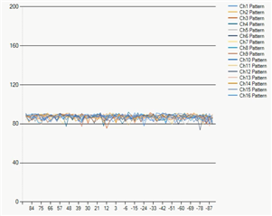
I tried to sketch the azimuth radiation pattern of our chip in DDMA mode, so I conducted some tests.

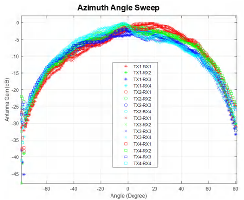
However, the results I obtained were significantly different from example of AMR2944 Evaluation Module User's Guide(Rev.A).

The radiation pattern below is our result (left) and example of document (right). 
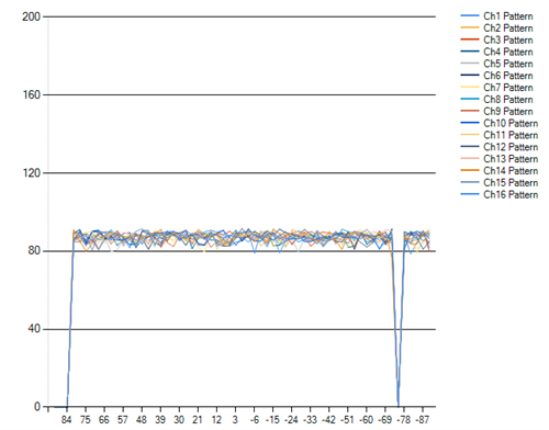
We developed based on SDK version 04.04.01.02.

In the experiment, the corner reflection was placed to 2.4 meters ahead ith 77.1GHz center frequency and 113Mhz bandwidth.We use rotation stage to ensure the relative positions of corner reflection and our chip.

At the RxChPhaseMeasure function in objectdetection.c, we extract azimuth samples of all channels (4Tx, 4Rx) associated with the strongest target selected in the function, and multiply them by the antenna calibration parameters before saving them to the rxChPhaseComp structure. 

The execution of below code, we setting the calibration_flag = 2

for (antennaIdx = 0; antennaIdx < staticCfg->numVirtualAntennas; antennaIdx++)
{
    scal = 32768./ antMagSq[antennaIdx] * sqrt(antMagSqMin);

    if(antennaIdx < staticCfg->numVirtualAntAzim){  //Azimuth

        if(calibration_flag == 1)// rx channel calibration, //TODO: Wood, Need change this magic number (1) to "FRAME_RUN_CALIB_MODE"
        {
            temp = (int32_t) MATHUTILS_ROUND_FLOAT(scal * detObjList[objIdxMax].azimSamples[antennaIdx].real);
            MATHUTILS_SATURATE16(temp);
            compRxChanCfg->rxChPhaseComp[antennaIdx].real = (int16_t) (temp);

            temp = (int32_t) MATHUTILS_ROUND_FLOAT(-scal * detObjList[objIdxMax].azimSamples[antennaIdx].imag);
            MATHUTILS_SATURATE16(temp);
            compRxChanCfg->rxChPhaseComp[antennaIdx].imag = (int16_t) (temp);
        }
        else //FRAME_RUN_DOPPLER_MODE
        {
            /* 3. Azimuth Antenna Calibration:
             * Multiply azimuth samples (azimSamples) of Doppler FFT with antenna calib params (antennaCalibParams)
             */
            azimSamples = (int64_t*) &detObjList[objIdxMax].azimSamples[0];
            samplesFlt2 = _dintsp(azimSamples[antennaIdx]);
            SamplesCalib[antennaIdx].ddat =  _complex_mpysp(samplesFlt2,antennaCalibParams[antennaIdx]);
            compRxChanCfg->rxChPhaseComp[antennaIdx].real = (int16_t)SamplesCalib[antennaIdx].cmplx.real;
            compRxChanCfg->rxChPhaseComp[antennaIdx].imag = (int16_t)SamplesCalib[antennaIdx].cmplx.imag;
        }
    }
    else{   //Elevation
        elevIdx = antennaIdx - staticCfg->numVirtualAntAzim;

        if(calibration_flag == 1)// rx channel calibration, //TODO: Wood, Need change this magic number (1) to "FRAME_RUN_CALIB_MODE"
        {
            temp = (int32_t) MATHUTILS_ROUND_FLOAT(scal * detObjList[objIdxMax].elevSamples[elevIdx].real);
            MATHUTILS_SATURATE16(temp);
            compRxChanCfg->rxChPhaseComp[antennaIdx].real = (int16_t) (temp);

            temp = (int32_t) MATHUTILS_ROUND_FLOAT(-scal * detObjList[objIdxMax].elevSamples[elevIdx].imag);
            MATHUTILS_SATURATE16(temp);
            compRxChanCfg->rxChPhaseComp[antennaIdx].imag = (int16_t) (temp);
        }
        else //calibration_flag == 2 , FRAME_RUN_DOPPLER_MODE
        {
            /* 4. Elevation Antenna calibration
             * Multiply elev samples with antenna calib params  */
            elevSamples = (int64_t*) &detObjList[objIdxMax].elevSamples[0];
            samplesFlt2 = _dintsp(elevSamples[elevIdx]);
            SamplesCalib[antennaIdx].ddat =  _complex_mpysp(samplesFlt2,antennaCalibParams[antennaIdx]);
            compRxChanCfg->rxChPhaseComp[antennaIdx].real = (int16_t)SamplesCalib[antennaIdx].cmplx.real;
            compRxChanCfg->rxChPhaseComp[antennaIdx].imag = (int16_t)SamplesCalib[antennaIdx].cmplx.imag;
        }
    }
}

The magnitude of all channels before we display is calculated using the following algorithm


Best regards

John

  • Hi John,

    Azimuth radiation pattern in the user guide is plotted using the TDM processing chain. You can refer to mmWave Production Testing Overview to know how we are performing the experiment.

    Please have look at below thread to understand how to get the antenna radiation pattern - 
    IWR6843ISK: How to get the antenna pattern - Continue. - Sensors forum - Sensors - TI E2E support forums

    Regards,

    Samhitha

  • Hi Samhitha,

    First of all, thank you for your response.
    According to our understanding, the azimSamples we use contain already demodulated information. Theoretically, we should be able to generate correct radiation pattern.

    And we believe that even though the pattern in the user guide are based on TDM, the results from DDMA should still correspond to the pattern based on TDM, rather than having the same magnitude at different angles as it currently does.

    If our understanding is correct, then is there might be some errors in our process?

    If not, then is there a way to output correct radiation pattern based on DDMA mode?

    Thanks,

    John

  • Hi John,

    Can you please check if you are using azimSamples of the correct range bin (detected object)? And for scaling can you use 16384 instead of 32768?
    Which version of SDK are you using?

    Regards,

    Samhitha

  • Hi Samhitha,

    I tried to changing the scaling from 32768 to 16384 and conducted a test.

    However, the results are the same as before the modification.

    Since modifying the scaling only affects the Rx calibration values becoming half of its original value, there won't be a significant difference in the trends of graph.

    I also check the range bins of picked azimSamples.

    Due to our settings, the range resolution is 1.33 meters, and the corner reflecter is placed 2.4 meters in front of the chip in our testing environment.

    In our result, the detected range of azimSamples are 2.67 meters, equivalent to a range bin of 2.

    Finally, we used version mmwave_mcuplus_sdk_04_04_01_02 of the SDK.

    Thanks,

    John

  • Hi John,

    I will check and get back to you in 2 days.

    Regards,

    Samhitha

  • Hi John,

    I have tested using TDM and noticed that there is a change in the magnitude of the samples at various angles. Can you please recheck the range resolution, and the range bin corresponding to the distance of the corner reflector? Can you also check the parameters for measureRangeBiasAndRxChanPhase command in your configuration as you are using DPC_ObjDet_RxChPhaseMeasure function for your calculations? I suggest you to perform the experiment using TDM by enabling only one Tx-Rx pair at a time.

    Regards,

    Samhitha