This thread has been locked.

If you have a related question, please click the "Ask a related question" button in the top right corner. The newly created question will be automatically linked to this question.

FDC2214: Active Shield

Part Number: FDC2214

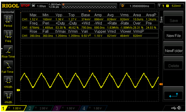
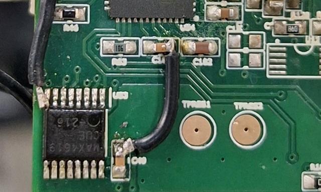
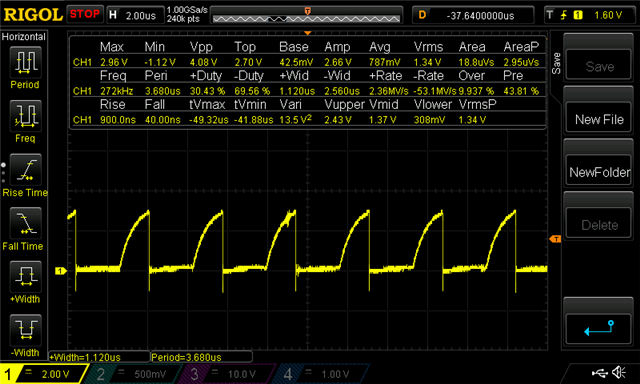
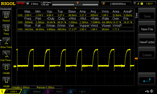
I have a problem with the active shield. I know from the datasheet the active shield signal should be the same with the excitation signal. But after i tried to connect a cable with shield, the active shield signal became a half for the amplitude, but the frequency was still the same. Could you guys elaborate about this issue?

  • Hey Specia,

    If I understood your prior post, for the latest test you connected the FDC2214 to another microcontroller and changed the SD and ADDR pin connections to GND and observed spikes while the same LC connections with the default TI microcontroller on our EVM did not yield spikes.  From that it made me think there might be a layout issue, particularly with the GND as the LC tank connections I presumed did not change.  The other reason I thought it might be related to the ground is that parts with oscillators or clocks can have noisy grounds when there is a weak ground connection (long wire trace acting as a parasitic inductor), especially if a decoupling cap is far from the supply and gnd pins.

    If you provide a picture of your setup or setups, that might help me better understand your situation.

    You previously asked whether there might be an issue with your code.  It sounds like there were instances in which you tested with the TI EVM and there were instances in which you tested with the STM microcontroller attached to the FDC2214 and in either case saw spikes.   As the code for each of these microcontrollers are different, I would expect the software code to not be identical, I would think the error would not be consistent. 

    As for your prior question regarding the reserved bits, those are for internal processes to facilitate operation or test of sub circuits within the device but are not necessary for the end user to know to get a measurement.

  • Hi Patrick,

    Anyways...pardon actually yesterday I tried other parameters setup on the FDC2214 EVM, still with electromechanical relay, but the spikes issue accidentally still happened while reading using the MSP controller board of the EVM. Then I added several ground wires on that, and surprisingly it fixed the spikes issue. 

    I've just tried to replace the MSP controller board by using my STM32F4 controller board, still used the setup with those additional ground wires, and yah it fixed the issue as well. I'm so glad the spikes issue was gone for electromechanical relay.

    And currently I'm pursuing to use an analog mux for the switching, after considerate long lifetime of the switching exactly. And yah I hacked an analog mux, even still with those additional ground wires as well, unfortunately I found the spikes issue again on the reading data. Do you think it is coming from the bad layout while using hacked board?

    But in the following picture, I probed the SCL signal, and it's kind of long rise time, right? FYI for the SDA-SCL pullup resistors I used 10kOhm.

    Then I replaced the pullups by using 2.2kOhm, and you could see that the rise time was getting better here, but still found the spikes issue.

    Are you noticing something?

  • Hey Specia,

    Glad we were able to make some progress and get that electromechanical relay working with the device.  It might not hurt to try and do a layout and get that in the queue while we are trying to work through spikes for this analog mux. You can get cheap boards relatively quickly through jlcpcb and pcbway.  Optimizing layout might reduce how many issues we run into.  If you choose to do so, I would try to have a solid ground plane between the FDC2214 and microcontroller similar to what we have on the evm, probably would not hurt to have the filter between the FDC2214 and the analog mux.  You could also possibly try having header pins on the mux path, so you could try daughter cards for testing out different muxes or different mux layouts.  For the mux you also likely need a good gnd connection with a supply decoupling cap near by; however, you need to be careful so that gnd is not closely overlapping your LC lines.

    As for the I2C lines, an even stronger pull up might not hurt.  I might suggest seeing if a 1.2kohmm helps.  Also, do you have any other devices on your i2c lines?  There might be some communication conflict if you do.

  • Hey Patrick,

    Currently, I am still preparing the PCB design for analog mux, I decided to use my actual PCB instead of hacked board.

    FYI, for the I2C lines, I put the FDC2214 only, other devices do not exist.

    Anyway, I have another question. Today I finished to populate my actual PCB with FDC2214 on it. And I obtained another issue. The issue is related to the sampling rate. While I was using the hacked board, the sampling rate could reach about 700 sps. But when I tested my actual PCB board, with the same code, the sampling rate reached below 100 sps (80 only). And I was noticing something on the status config register (0x18), the value showed 0x48 (0000 0000 0100 1000), the value of bit 6 is 0. I think it is normal (based on the datasheet page 32). Do you understand about this issue? Any suggestions? I tried to check the interrupt signal using oscilloscope, and it showed 12.8 milliseconds for the period while the hacked board gave 1.28 milliseconds (about 1/10 times faster).

  • Hey Specia,

    For bit 3 and bit 6 in register 0x18 to be 1 at the same time seems normal, as both  indicate a conversion result is ready.  Presuming the register configuration remained the same between boards, the discrepancy might stem from your path to the LC tank.  If you have a larger effective inductor or larger capacitor, I would expect the resonant frequency to decrease. I would expect longer trace or cable lines to increase inductance.  For the capacitance, you might see differences if you modified the pad size or the board material. 

  • Hi Patrick,

    Actually the sampling rate issue was coming from my board, pardon I gave wrong connection for interrupts of stepper motor controllers on my board, it's related to the FDC2214 interrupt in the code. The wrong connection caused the slower sampling rate.

    Here I also continued to try the analog mux for the switching, and surprisingly with my actual PCB, the spikes issue didn't appear Slight smile

    But currently i am still checking other issues that may be coming up.

  • Hey Specia,

    Glad you were able to sort out the sampling issues and you are not seeing spikes.  Let me know if you run into further issues.

  • Hey Patrick, 

    Long time no visit here

    Just a random question, the FDC2214 VDD is tied to +3V3. How can the voltage amplitude be more than 3V3? Is that normal? *you could see in the signal picture i posted a couple weeks ago.

    And I need your suggestion. Currently in my board, we use +-5V for the OpAmp supply. The OpAmp is to generate the guard signal. Regarding use this OpAmp, we have to use +-5V for the supply. I've ever tried to use single supply (+5V and GND) but obtained the output signal like the following picture.

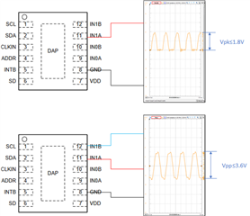
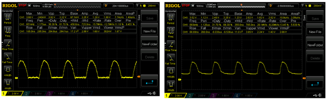
      (left = the input, right = the output)

    In my board, power regulator +-5V have to use several inductors (it's boost converter), and it won't be compatible with my mechanical requirements, which are needing component less than 1mm for the height to avoid crash during motor motion. If I could use single supply for the OpAmp, I don't need to use that OpAmp anymore. Could you suggest me the type of the OpAmp even other suggestions?

    I've ever tried another OpAmp, but obtained an issue, it seems the output signal is like the charge cycle of the C load, like the following picture.

  • Ohya for the switching using multiplexer, after I plugged the long cable, somehow I still found spikes issue on the data reading intermittently while using lower current for the current drive, at 0.867 mA.

    Then I tried to add several ground wires to the multiplexer, like the following picture.

    And it fixed the spikes issue on the setup, using 0.867 mA. But it didn't work for current drive at 0.356mA and lower. Do you think that the spikes issue is caused by weak GND connection as well as previously? Should I add several GND traces in the board design?

  • Hey Specia,

    Exceeding 3.3V does seem like it should not be possible. At the FDC INx pins, I would expect a peak voltage of 1.8V.  If it is higher than that, it could be some sort of ground issue.  Are you probing gnd directly at the FDC gnd pin or at some other place on the ground net?

    To the best of my knowledge, all op amps need a positive and negative supply if the signal you are trying buffer is positive and negative.  Maybe an alternative to your switch mode power supply could be a 555 timer circuit for producing the negative rail.  Such a circuit can be found here.

    As additional wires to gnd seem to be helping, it looks as though you have several weak ground connections.   If you consider revising the board design, I would suggest looking at each interconnecting board trace as a nonzero resistor, and the skinnier and longer it is, the higher its resistance.  If you notice a lot of long skinny traces for your board layout, that could be contributing to some of the issues you are seeing.  Ideally you want to have large ground plane with with minimal resistance between different ground pins.

  • Hey Patrick, for the amplitude of excitation signal exceeds 3.3V, I think we might have different measurement concepts on an oscilloscope.

    Depends on the pic above, what is the meaning of Vpeak mentioned on the FDC2214 datasheet? Is Vpeak same with Vmax? or Vtop?

    And if the Vpeak mentioned on the datasheet is Vtop (based on the pic above), and the signal gave a rest wave under 0V (negative voltage), could I use single supply for the voltage and ignore the negative voltage of the wave?

    Btw, does FDC2214 has simulation model? Such TINA model or other simulator...?

  • Hello Specia,

    This diagram illustrates my thoughts on Vpk and Vpp relative to probe connections.  The device needs to see the negative voltage.  If you are unable to provide  a negative voltage, perhaps you can try offsetting the FDC2214 gnd pin to >1.8V. If you have a 5V supply on your board, 2.5V might be worth considering. However you might need some additional circuitry for your communication signals if you go this route.  As of now, we do not have TINA model for this device.

  • Hi Patrick,

    Did you probe it using DC coupling instead of AC coupling?

    For offsetting the FDC2214 signal, since I am using single-ended mode, the signal should be similar to your top picture (it's halfwave signal DC coupling). Doesn't it matter if I will use single supply (instead of dual supply for the OpAmp) regarding the signal may be over 0V..? 

  • Hey Specia,

    I was using DC coupling.  Single ended in this case refers to whether you have only a conductive plate at INxA or INxB, whereas differential would have plates at both INxA and INxB. Your FDC LC tank signal should still be straddling FDC gnd.  So if you use a single supply with half of the oscillator signal below gnd, you are going to have issues.

  • Hello Patrick, 

    Sure, I will keep the dual supply.

    Btw, related to the spikes issue several times ago, actually I found the best current drive setup to avoid the spikes issue while using relay even the multiplexer as the switching. My test says the smaller current drive, the less frequently spikes come. Could you elaborate the correlation about this to the ground connection? Could I say that the smaller current drive needs a large GND plane (strong ground connection) so that the connection resistance is small..?

  • Hey Specia,

    Weak ground connections increase resistance between different ground nodes or gnd pins.  However long gnd traces also introduce more inductance between nodes as well.  Based on the inductor formula Ldi/dt=V, we can expect that increasing L or the change in current for a clock period can lead to higher voltage potentials. Similar to resistors, inductors in parallel should have a lower total inductance, which might help explain how the multiple ground connecting wires helped in one of your other threads.

  • Hi Patrick,

    Do you guys have latest update for layout examples, in order I can use it as a reference, since I found the spikes issue while using analog mux and relay for switching even when I used the eval-module a couple weeks ago?

  • Hello Specia,

    We have not created any new reference designs for this device.  The EVM is the example we provide.  If you have a layout you would like reviewed, we can look it over and provide feedback on what we think might be an issue. If you are concerned with sharing your design, there is a way in this forum to send private messages.

  • Hey Patrick,

    About interference testing for this sensor, several days ago i tried to set a conductive objects close to the sensor as aggressors. I checked using oscilloscope the excitation freq of the sensor is 912.82KHz. I drove sine wave with 962.82 KHz (912.82 KHz + 50 KHz) for the aggressors. Seems so weird since the interference is 0 even I tried to move the sensor (make it far and close to the aggressors). Are you noticing something with freq 962.82 KHz? When I tried to touch the probe which connected to the sensor, it still can sense my touch. This is interesting due to use aggressor freq at 1012.82KHz (912.82 KHz + 100 KHz) we still could see the interference during moving. We did this test expecting to reduce the interference noise during movement by set the aggressor in different freq signal.

  • Hey Specia,

    Are you saying that you observe no response when you place conductive objects near the shield plate or the sensing plate?  And are you saying this just occurs at an excitation frequency of 962.82kHz?

  • Hello Patrick,

    I mean the sensor is working too well without interference, but it is only when I set the aggressors (conductive) at freq 962.82kHz sine wave. 962.82kHz is freq of the aggressors while the freq of the sensor is 912.82kHz (I add 50kHz of it).

    Is it a harmonic phenomenon or something?

  • Hi Specia,

    Thank you for posting to the sensors forum. 

    Today is a holiday in the US and Patrick is out of office. We will do our best to provide a response by end of day July 5. 

    Best regards,

    Jesse

  • Hello Specia,

    So are you saying that your device can detect your intended object when operating at reference frequency of 912.82kHz and nearby conducting aggressors have frequency of 962.82khz;  however, when aggressors have any other frequency, the active shield fails to filter or eliminate their signal from your sensing lines?  What is the your intended target you want to sense? 

  • Hi Patrick,

    My target is 912.82kHz. FYI, currently i can avoid interference issue for the sensor by setting the current drive lower. I'm glad I obtained more than 10 SNR. Set the current driver lower is working well on my application, thanks :)

  • Hello Specia,

    Glad to know you are able to avoid the interference issue now.  Let me know if you run into any further issues.